Maker Pro
Maker Pro

Boost converter

Karthik rajagopal

May 9, 2016
257
Joined
May 9, 2016
Messages
257
Hi all,
I am working with battery powered project for which I bought a XL6009 based boost converter module. The output was fluctuating (around 30 V) and never settled (even after adjusting the pot), so, I connected it to my lab power supply. The power supply went from constant current to constant voltage only after raising the current limit to 900 mA (boost converter input was 4V and output was set to 5V). I know boost converters have inrush current but didn't expect it to be this high. Since I don't have an extra module, I am unable to ascertain if the board is working correctly. Need advice on how to test the board.

Thanks in advance.
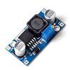
1683442665139.png
 
Last edited:

Harald Kapp

Moderator
Moderator
Nov 17, 2011
13,747
Joined
Nov 17, 2011
Messages
13,747
The XL6009 data in the datasheet is specified at 500 mA output current. Possibly the regulator is not stable without a load. For testing add an output resistor such that at least 100 mA output current is drawn, then check the regulation again.
 

Karthik rajagopal

May 9, 2016
257
Joined
May 9, 2016
Messages
257
The XL6009 data in the datasheet is specified at 500 mA output current. Possibly the regulator is not stable without a load. For testing add an output resistor such that at least 100 mA output current is drawn, then check the regulation again.
Thanks for the reply. I connected a 47 ohm resistor at the output to draw the suggested current. The voltage regulation failed and the voltage went below 5V (around 2 V) as the converter was unable to provide the 100mA output load current. The lab power supply was again in CC mode (with limit set to 1.5 A).
 

Delta Prime

Jul 29, 2020
1,985
Joined
Jul 29, 2020
Messages
1,985
Your unit is working properly.
What output load are you using? Did you wind your own inductor L2?
The 33uH inductor that is L1, is the inductor which is responsible for the Buck mode of operation whereas the Inductor L2 is used for the Boost mode inductor.
during the boost mode when the input voltage is less than the output voltage the inductor L2 gets charged up and provides the load current during switch off condition.
The output load is set with a value of approximately 700-800mA of current. You can change the output diode to increase the output current.
The Feedback threshold voltage is 1.25V, the voltage divider can be set according to this feedback voltage for configuring the actual output.
Vout= (Vin x R2) / (R1 + R2).
Output voltage fluctuates +/-5% . This is due to the high DCR value of inductors and the unavailability of the heat sink in the XL6009. Adequate heat sink and proper components can be useful for stable output. ;)
 

Karthik rajagopal

May 9, 2016
257
Joined
May 9, 2016
Messages
257
Your unit is working properly.
What output load are you using? Did you wind your own inductor L2?
The 33uH inductor that is L1, is the inductor which is responsible for the Buck mode of operation whereas the Inductor L2 is used for the Boost mode inductor.
during the boost mode when the input voltage is less than the output voltage the inductor L2 gets charged up and provides the load current during switch off condition.
The output load is set with a value of approximately 700-800mA of current. You can change the output diode to increase the output current.
The Feedback threshold voltage is 1.25V, the voltage divider can be set according to this feedback voltage for configuring the actual output.
Vout= (Vin x R2) / (R1 + R2).
Output voltage fluctuates +/-5% . This is due to the high DCR value of inductors and the unavailability of the heat sink in the XL6009. Adequate heat sink and proper components can be useful for stable output. ;)
Thanks for the reply.
I am using a commercial board and didn't build my own. I have attached the image in #1.
Mine is a boost converter and not a buck-boost module.
 

Karthik rajagopal

May 9, 2016
257
Joined
May 9, 2016
Messages
257
An update,
I read the minimum input voltage of the XL6009 based boost converter to be 5V. So, I changed my input voltage to 6V and set the output as 10V. Still each time during startup, it goes into the random higher voltage and settles only when provided with the 900 mA of startup current.
 

bertus

Moderator
Nov 8, 2019
3,330
Joined
Nov 8, 2019
Messages
3,330
Hello,

The datasheet shows a minimum input voltage of 5 Volts, wich is also stated on this page for the module:
Having a lower input voltage may give problems.

Bertus
 

Attachments

  • XL6009-XLSEMI.pdf
    177.4 KB · Views: 1

Karthik rajagopal

May 9, 2016
257
Joined
May 9, 2016
Messages
257
What is the load?
Does it settle to the proper voltage and lower input current?
I have not connected any load at the output, just the voltmeter. After supplying it with the 900 mA current, It settles down to the proper set voltage and current drops to 4 mA of quiescent current.
 

Karthik rajagopal

May 9, 2016
257
Joined
May 9, 2016
Messages
257
Hello,

The datasheet shows a minimum input voltage of 5 Volts, wich is also stated on this page for the module:
Having a lower input voltage may give problems.

Bertus
Thanks for the reply. I tried increasing the voltage but ended up with the same result. (Please refer msg #6)
 

Karthik rajagopal

May 9, 2016
257
Joined
May 9, 2016
Messages
257
Then it sounds like normal initial inrush current at the converters startup.
Is there a way to reduce the inrush current?
My load will be a small LED strip which will draw 30mA @ 5V. Since the output current is low (hence a lower output ripple ), will replacing the input / output filter caps with a lower value help solve this issue?
 

Delta Prime

Jul 29, 2020
1,985
Joined
Jul 29, 2020
Messages
1,985
will replacing the input / output filter caps with a lower value help solve this issue
No! The cheapest and easiest way to solve your problem is connecting an NTC negative temperature coefficient resistor in series to limit the in Rush current
You see the capacitors are the cause of the in Rush current without it wouldn't be a boost converter the capacitors charge from 0 volts to the input voltage via the diode.
 

Karthik rajagopal

May 9, 2016
257
Joined
May 9, 2016
Messages
257
No! The cheapest and easiest way to solve your problem is connecting an NTC negative temperature coefficient resistor in series to limit the in Rush current
You see the capacitors are the cause of the in Rush current without it wouldn't be a boost converter the capacitors charge from 0 volts to the input voltage via the diode.
Thanks for suggesting. I will try this method and update.
 

Karthik rajagopal

May 9, 2016
257
Joined
May 9, 2016
Messages
257
No! The cheapest and easiest way to solve your problem is connecting an NTC negative temperature coefficient resistor in series to limit the in Rush current
You see the capacitors are the cause of the in Rush current without it wouldn't be a boost converter the capacitors charge from 0 volts to the input voltage via the diode.
Tried it out with NTC in series with the input and still got the same output. When I increased the input voltage (at around 7 V), the converter functioned properly and the inrush current came down to 350mA. I guess the XL6009 switching IC is malfunctioning.
Anyway I would need an alternate as my battery can supply only a maximum of 4V.
Found out that MT3608 based boost converters can work with supply voltage as low as 2V. Will give that a try.

Thank you all for helping me out with this issue
 
Top