usr:[email protected]
- Apr 27, 2019
- 4
- Joined
- Apr 27, 2019
- Messages
- 4
I am currently working on a final resubmission for an electronic engineering BTEC level 3 assignment. I have posted the original question, answer and tutor feedback below. Just wondering if anyone can make sense of the feedback and give guidance as to how to correct the answer.
T6.
As an alternative to the AC system in task 5, you have also been asked to produce a circuit design that can control the speed and direction of the conveyor using a DC motor drive system. With reference to circuit layout drawings and research sources, explain how it operates. (400 words)
Answer:
Modern conveyor systems use brushless DC motors with sensors, which offer sophisticated seed control. One method of speed control is trapezoidal commutation, which involves controlling the current in two phases at a time, with the third phase disconnected.
PWM (pulse width modulation) is used in this speed control system. PWM involves varying the input voltage by generating a series of pulses and is the operating principle behind choppers (electronic static power device, a high speed switch that connects/disconnects load from voltage supply to get pulses). The chopper’s mark-space (Ton/Toff) ratio is controlled by thyristors (electronic switches) which vary the pulses’ average voltage (Vout = (Ton/(Ton/Toff)) x Vin). PWM varies the average voltage and current flow in the coils and so the motor’s speed and torque.
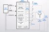
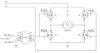
The chopper circuit, uses a number of MOSFETs (metal-oxide-semiconductor field-effect transistor). A pair of MOSFETs controls one phase of the motor, so for a 3-phase BLDC motor 3 pairs of MOSFETs are required (4). These can be arranged in the format shown in the circuit diagram.
The above diagram shows the layout of the speed drive circuit board. In this circuit the micro-controller PWM signals six inputs to the IC. Each of these inputs corresponds to the six MOSFETs (5). The three Hall effect sensors send signals to the MCU to control when it commutates (5).
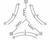
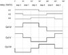
For every electrical revolution, a six-step commutation process is used (6). The rotor has two pairs of permanent magnets, meaning that two electrical revolutions spin the rotor once (6). The diagrams below show the rotor coil arrangements and corresponding Hall effect sensor outputs and voltages.
Out of the two phases, which are energised during each step, one phase provides the current, and the other the current return path (6). The micro controller automatically controls which switches in the MOFSETs must be open/closed to provide negative/positive current to the two coils, the third coil will remain open (6). In more detail, the MOSFETs may be in the following states: High (top switch is closed, bottom switch is open), Low (top switch is open, bottom switch is closed), or OFF (both switches are open).
In order to complete the drive system a regulated MOSFET power supply is required, which usually includes: step-down transformer, gate fault handling/driver control and timing/control logic (6).
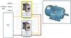
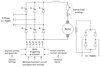
The direction of the motor can be reversed through interchanging the connection of any two power supply leads to the motor. The circuit is connected to a PLC, which can automatically control the direction through pre-programmed timing logic. The contactors interchange the wiring on the load side which allows a neater set-up. The circuit is shown below.
One set of wires is fed through a contactor and another set through another contactor. These contactors require an interlocking device to prevent the contactors being operated simultaneously, this can either be a mechanical or electrical interlock. This circuit utilises an electrical interlock in the form of NC auxiliary contacts in each contactor. The PLC supplies the auxiliary contacts, each of which is wired in series with a coil, and controls the opening/closing of them and so the energisation of the coils. When one contactor is operating its auxiliary contact is opened, de-energising the other coil, preventing the other contactor from operating (7).
Tutor feedback:
T6 some interesting stuff here, but it is unclear from your diagrams how the 3-ph supply is converted to PWM dc using thyristors. Also electronic direction control is not shown.
The only supply to a workshop will be 3-ph ac so you need to start with this and then convert to some form of pwm dc,( using thyristors is a common way to do this).
To change motor direction there should be a simple electronic control circuit that controls the dc supply to the motor and not a PLC.
Anyone have suggestions for a speed control circuit and a separate direction control circuit? It is for an automatic conveyor so has no push buttons/manual switches. Any help would be appreciated.
T6.
As an alternative to the AC system in task 5, you have also been asked to produce a circuit design that can control the speed and direction of the conveyor using a DC motor drive system. With reference to circuit layout drawings and research sources, explain how it operates. (400 words)
Answer:
Modern conveyor systems use brushless DC motors with sensors, which offer sophisticated seed control. One method of speed control is trapezoidal commutation, which involves controlling the current in two phases at a time, with the third phase disconnected.
PWM (pulse width modulation) is used in this speed control system. PWM involves varying the input voltage by generating a series of pulses and is the operating principle behind choppers (electronic static power device, a high speed switch that connects/disconnects load from voltage supply to get pulses). The chopper’s mark-space (Ton/Toff) ratio is controlled by thyristors (electronic switches) which vary the pulses’ average voltage (Vout = (Ton/(Ton/Toff)) x Vin). PWM varies the average voltage and current flow in the coils and so the motor’s speed and torque.
The chopper circuit, uses a number of MOSFETs (metal-oxide-semiconductor field-effect transistor). A pair of MOSFETs controls one phase of the motor, so for a 3-phase BLDC motor 3 pairs of MOSFETs are required (4). These can be arranged in the format shown in the circuit diagram.
The above diagram shows the layout of the speed drive circuit board. In this circuit the micro-controller PWM signals six inputs to the IC. Each of these inputs corresponds to the six MOSFETs (5). The three Hall effect sensors send signals to the MCU to control when it commutates (5).
For every electrical revolution, a six-step commutation process is used (6). The rotor has two pairs of permanent magnets, meaning that two electrical revolutions spin the rotor once (6). The diagrams below show the rotor coil arrangements and corresponding Hall effect sensor outputs and voltages.
Out of the two phases, which are energised during each step, one phase provides the current, and the other the current return path (6). The micro controller automatically controls which switches in the MOFSETs must be open/closed to provide negative/positive current to the two coils, the third coil will remain open (6). In more detail, the MOSFETs may be in the following states: High (top switch is closed, bottom switch is open), Low (top switch is open, bottom switch is closed), or OFF (both switches are open).
In order to complete the drive system a regulated MOSFET power supply is required, which usually includes: step-down transformer, gate fault handling/driver control and timing/control logic (6).
The direction of the motor can be reversed through interchanging the connection of any two power supply leads to the motor. The circuit is connected to a PLC, which can automatically control the direction through pre-programmed timing logic. The contactors interchange the wiring on the load side which allows a neater set-up. The circuit is shown below.
One set of wires is fed through a contactor and another set through another contactor. These contactors require an interlocking device to prevent the contactors being operated simultaneously, this can either be a mechanical or electrical interlock. This circuit utilises an electrical interlock in the form of NC auxiliary contacts in each contactor. The PLC supplies the auxiliary contacts, each of which is wired in series with a coil, and controls the opening/closing of them and so the energisation of the coils. When one contactor is operating its auxiliary contact is opened, de-energising the other coil, preventing the other contactor from operating (7).
Tutor feedback:
T6 some interesting stuff here, but it is unclear from your diagrams how the 3-ph supply is converted to PWM dc using thyristors. Also electronic direction control is not shown.
The only supply to a workshop will be 3-ph ac so you need to start with this and then convert to some form of pwm dc,( using thyristors is a common way to do this).
To change motor direction there should be a simple electronic control circuit that controls the dc supply to the motor and not a PLC.
Anyone have suggestions for a speed control circuit and a separate direction control circuit? It is for an automatic conveyor so has no push buttons/manual switches. Any help would be appreciated.