Maker Pro
Maker Pro

Bistable Multivibrator

Albe

Mar 11, 2016
7
Joined
Mar 11, 2016
Messages
7
Hi Folks,

Newbie electronics geek here. I've been slowly dabbling with micro-electronics and decided I wanted to attempt to build a single switch/multi-location on-off controller for the air compressor in my garage. Perhaps a bit overkill, but that's me!

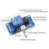
In order to make this work the way I want, I purchased a "1 channel latching relay module w/ Touch Bi-Stable Switch MCU control" from Amazon. After wiring up my circuit, everything works great except the switching device seems to sometimes not trip or over trip the electronic control. I'm basically using this small unit to trigger a high-current contactor to run the air compressor.

What's happening is this: I have a single contact momentary switch. When I depress the switch, it trips the flip-flop action of a 555 timer and energizes the larger contactor. Sometimes when I depress the switch, the contactor will bounce on/off/on/off a few times and stay in whatever state it was previously in before I pushed the switch. Its as if I pushed the switch a few times rather than once.

With my limited knowledge of electronics and how this works, I'm wondering if I'm getting come kind of ghost current that's triggering or setting off the timer circuit and making it flip-flop and flop-flip again very fast, several times. Is there anything I can/should put in series with the switch (i.e. a cap or resistor) to maybe smooth out the action of the switch ? This is the only thing I can think of.

Any help is much appreciated and thanks in advance! :)
 

Attachments

  • hiletgo2.jpg
    hiletgo2.jpg
    94.5 KB · Views: 27
Last edited:

Harald Kapp

Moderator
Moderator
Nov 17, 2011
13,719
Joined
Nov 17, 2011
Messages
13,719
When I depress the switch, it trips the flip-flop action of a 555 timer and energizes the larger contactor.
This board seemingly uses a pic15f04 microcontroller, not a 555.
The effect you describe to me sounds like contact bounce of the momentary switch. Ideally the software in the controlle should debounce the switch, but the software may be badly written or your momentary switch creates an excessive amount of bounce.
Can you try another momentary switch?
You can also try to reduce contact bounce by adding a small capacitor (e.g. 100 nF) in parallel to the momentary switch. Note that this is not proper debouncing but given that you very likely are not able to modify the software it may be a jury rigged workaround.
 

Harald Kapp

Moderator
Moderator
Nov 17, 2011
13,719
Joined
Nov 17, 2011
Messages
13,719
I'm sorry, the type is STC15f104.Is hould have tried harder to decipher the print on the chip.
 

AnalogKid

Jun 10, 2015
2,892
Joined
Jun 10, 2015
Messages
2,892
Hard to believe a uC-based switch interface would not have debouncing built into the firmware.

Link to the board vendor site so we can read all about it?

ak
 

Harald Kapp

Moderator
Moderator
Nov 17, 2011
13,719
Joined
Nov 17, 2011
Messages
13,719
Hard to believe a uC-based switch interface would not have debouncing built into the firmware.
I'm sure there is, but maybe not good enough for th external moemntar yswicth the op uses.
@Albe : does the phenomenon appear with the built-in test button, too?

Link to the board vendor site so we can read all about it?
See e.g. here. This module is offered on many sites. The description is scarce (a well meaning expression). E.g.:
Chips made ??using stable and reliable control , stable and reliable performance , strong anti-interference , not false triggering , performance is superior than the CD4013 ;
 

Bluejets

Oct 5, 2014
6,920
Joined
Oct 5, 2014
Messages
6,920
555 style may not be quite so susceptible to noise, long cable runs, whatever.
 

WHONOES

May 20, 2017
1,217
Joined
May 20, 2017
Messages
1,217
A 4013 can be encouraged to do exactly what you want.
 

Albe

Mar 11, 2016
7
Joined
Mar 11, 2016
Messages
7
Hi All, Thank you for the replies.

I was messing around again with the circuit last night and I had removed the power feed to the electrical contactor I'm using post remote switch. (I'm using the remote switched relay to power a high-current electrical contactor). When I removed the power inlet to the contactors electromagnet, the switch bounce was eliminated.

This got me thinking... could the 120v solenoid somehow be creating a back-current to the smaller relay making the relay bounce on/off? I'm still new at this so I'm piecing things together as I go along. Is there maybe a way I can incorporate a diode onto the 120v line? I realize that might not work on alternating current but not sure.

For what it's worth, i'm using the bistable multivibrator which controls a low power relay (all part of the pre-made component) which when the contacts close they energize a 120v electrical contactor.

Thanks for all the help!
 

Alec_t

Jul 7, 2015
3,590
Joined
Jul 7, 2015
Messages
3,590
Is there maybe a way I can incorporate a diode onto the 120v line? I realize that might not work on alternating current but not sure.
That depends on the contactor's properties. If the contactor coil is designed to be powered by AC only, then using a diode would effectively reduce the impedance of the coil and could result in the coil burning out.
 

Harald Kapp

Moderator
Moderator
Nov 17, 2011
13,719
Joined
Nov 17, 2011
Messages
13,719
Try a low value X/Y capacitor across the output contacts of the timer's relay. 2.2 nF / 400 V, specifically designated X/Y type.
This capacitor may reduce the induced noise from switching the contactor. Be aware, however, that even in the timer's off state a capacitive current is able to flow. With 2.2 nF it will not suffice to operate the contactor, but it will allow dangerous voltage to be present at the contactor's coil even when off.
 

hevans1944

Hop - AC8NS
Jun 21, 2012
4,880
Joined
Jun 21, 2012
Messages
4,880
Here is a link to an Amazon page that has lots of image views, complete with on-screen magnifier, for what is branded as a
Wrisky 1 Channel 12V Latching Relay Module with Touch Bistable Switch MCU Control
The "part number" is Wrisky0386. No price is given, and Amazon says it is out of stock and they don't know when (or if ever) it will be in their stock again.

I don't know about the rest of the team here, but I would be somewhat hesitant about buying anything from a company named "Wrisky" no matter how sweet a deal was offered.

I am all for small microprocessor designs like this one, especially those dedicated to a single function like this one appears to be, but I would prefer that it be "open source" so I can farkle with the code if need be. Better yet would be a small kit with tiny, itsy-bitsy parts already soldered on the board, and larger through-hole parts like sockets and wire terminations left for me to install and solder in place, so I feel I have actually accomplished something. And of course some easy and simple way to program or re-program the processor.

Hmmm. Sounds like this could be a business opportunity for yours truly if I can apply the KISS principle to the kits and market them as a "learning experience" in electronics. Might have to include some free printed instructions, like Mr. Forrest Mims did for the Radio Shack "learning electronics" kits, although I am sure he was compensated for his efforts. I grew up learning electronics at an early age from Forrest Mims.

With all that said, there are plenty of push-on/push-off push-button circuits out there to choose from. If all you want to do is turn an air compressor on and off, I would personally opt for TWO push-buttons that set and clear an RS flip-flop (of which there happens to be one in every 555 timer IC) made either from an integrated circuit or two discrete transistors driving a small DC relay, whose contacts then control the much larger AC contactor for the compressor motor. Same circuit that you posted, only without the microprocessor. You can come back to that approach later after you have learned some more electronics. Meanwhile, try this link for some ideas. You could also delete the "fc-73" qualifier from the Google search string for that link and obtain similar, possibly better results. Most of all, remember to have FUN. Electronics is supposed to be FUN!
 

hevans1944

Hop - AC8NS
Jun 21, 2012
4,880
Joined
Jun 21, 2012
Messages
4,880
I'm sorry, the type is STC15f104. Ishould have tried harder to decipher the print on the chip.
Not your fault that @Albe uploaded an image with poor resolution. The Amazon website has much better (and more) images. See my post #12. One of them clearly shows the IC to be an STC 15F104E, a microprocessor with 4K (bytes?) of program memory. Switch bounce (and induced noise pick-up) is easily removed with proper programming techniques, which obviously were not applied to this particular implementation.

Human response time is so sloow compared to contactor switching noise and switch bounce times that it is almost trivial to remove both of these "interference" problems from a simple switch control. Who cares if it take a few tenths of a second for a push-button switch to change an air compressor motor from off to on or vice versa? Even a one second delay would probably be tolerable if that were necessary to avoid false triggering. And it is, again, trivially easy to make it a requirement that the push-button switch be held activated for a minimum period of time before it is recognized as a valid change-in-state command. All these considerations, and probably some I forgot to mention, make it possible to implement using proper software and a small microprocessor a "bullet-proof" push-button switch, using just simple single-pole, single-throw, normally-open switches.
 

Albe

Mar 11, 2016
7
Joined
Mar 11, 2016
Messages
7
Try a low value X/Y capacitor across the output contacts of the timer's relay. 2.2 nF / 400 V, specifically designated X/Y type.
This capacitor may reduce the induced noise from switching the contactor. Be aware, however, that even in the timer's off state a capacitive current is able to flow. With 2.2 nF it will not suffice to operate the contactor, but it will allow dangerous voltage to be present at the contactor's coil even when off.

Hi All,
After a long hiatus (this project got put on the back burner as I was getting frustrated as to what to do next) I've decided to continue trying to get this circuit to work as I want it to. Per Harald Kapp's recommendation, I put an x2 capacitor (2.2nf) across the contactor coil (one leg to the hot/input side of the coil, one leg on the neutral side of the coil) and for the most part this has eliminated the "switch bounce" symptoms. I use quotes because I don't believe the symptoms are truly switch bounce. IF the contactors coil is disconnected, there is no "switch bounce" leading me to believe its' the contactor somehow 'backfeeding' the control relay... There is still some "switch bounce" symptoms but no where near as often as it was happening before. The cap seemed to eliminate a lot of it.

SO my next thought is to maybe increase the size of the capacitor. I have two other sizes up from the 2.2nf (I have 22nf and 220nf capacitors that came as a package deal). Would there be any adverse effect by using something bigger? I even have a 1uF x2 capacitor I salvaged from a computer power supply I can try using.

Also, for what it's worth, I'm putting the cap across the contactor coil contacts. Should I put it across the entire incoming power line instead?

Lastly, if this doesn't work, I may try and build a 555 timer flip-flop or as someone recommended above a 4013 flip-flop.

Thanks all for the help. This has been a fun learning experience for me :)
 
Last edited:

Bluejets

Oct 5, 2014
6,920
Joined
Oct 5, 2014
Messages
6,920
How far is it from your switching position/ positions to the compressor location?

It is quite feasible that one of the single channel wireless relay units would suffice.

They can be set as toggle or on-off with button press and have a relay output that would interface with your compressor contactor.
Also the receiver units are available in a variety of operating voltages from low voltage dc to 220v ac .
Only cost a few buck also.

https://www.ebay.com.au/itm/Wireles...584138?hash=item4204747b4a:g:mhwAAOSw0tNdJFFu

Don't think the 3klm range would ever be a reality but should be ok for maybe 50m or so.

Naturally the question I think all are curious about is why would you need to switch a compressor on-off from multiple remote locations....?
 
Top