Hi All,
I am working on a project, and i'm basically finished but i'm not sure that I don't have a problem with my setup. Forgive my ignorance here, I'm new with this stuff.
I have a radio scanner that has a fire tone-out mode, where it will listen to a county dispatch channel and only activate when my station gets a dispatch. I am using the audio output (4V AC) to activate a relay with a timer to ring a bell and flash a light for four seconds. Simple right?
Here are some facts.
* The radio is powered by a 13.8V DC .75A transformer that plugs into my AC wall outlet
* The relay/load are powered by a 12V DC 3A transformer that plugs into AC wall outlet
* The relay is rated for 12V, 5A
* My load consists of a bell (12V, .8A) and a light (12V, .2A)
My audio out from the radio scanner is a 3.5mm stereo jack that leads to 2x RCA connectors. When the radio is active, and i put my voltage meter on the male end of one of the RCA connectors and I put the ground lead on the metal radio case, I see 4-5V AC, when the radio is silent i see none.
I was dismayed when i originally set this up that the audio was not activating the relay. upon putting my meter on the relay I found that the (-) DC wire in my relay was not a sufficient ground for the AC voltage coming from the audio wire- I got no reading. Thus, the relay didn't detect any voltage change and never activated.
I spoke to my neighbor who has a background as an electrician and he immeditaaly identified the problem as a ground loop. He said that if i bonded the ground on the scanner to the (-) from the relay/power source that It would solve my problem. I threw an alligator clip between the two and sure enough... it works great.
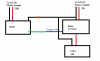
or does it? Below is a simple diagram of what i have. Red is DC+, Black is DC-, Green is my audio cable and blue is the trigger wire for the relay.
I'm worried about a load (bell and light) pulling 1Amp of current and that current having the ability to ground through a radio that is probably only ever expecting to encounter .75A (or less) of current. I'm worried i'm going to ruin the radio.
In the diagram i have an X. Is this a sensible place to put a resistor to step the amperage down to below .75A? The load would still operate because any current in excess of .75A would go to the (-) of the power supply. Am I way off?
Any alternate suggestions for getting this setup to work other than bonding the grounds like this?
Thanks in advance!
A;ex
I am working on a project, and i'm basically finished but i'm not sure that I don't have a problem with my setup. Forgive my ignorance here, I'm new with this stuff.
I have a radio scanner that has a fire tone-out mode, where it will listen to a county dispatch channel and only activate when my station gets a dispatch. I am using the audio output (4V AC) to activate a relay with a timer to ring a bell and flash a light for four seconds. Simple right?
Here are some facts.
* The radio is powered by a 13.8V DC .75A transformer that plugs into my AC wall outlet
* The relay/load are powered by a 12V DC 3A transformer that plugs into AC wall outlet
* The relay is rated for 12V, 5A
* My load consists of a bell (12V, .8A) and a light (12V, .2A)
My audio out from the radio scanner is a 3.5mm stereo jack that leads to 2x RCA connectors. When the radio is active, and i put my voltage meter on the male end of one of the RCA connectors and I put the ground lead on the metal radio case, I see 4-5V AC, when the radio is silent i see none.
I was dismayed when i originally set this up that the audio was not activating the relay. upon putting my meter on the relay I found that the (-) DC wire in my relay was not a sufficient ground for the AC voltage coming from the audio wire- I got no reading. Thus, the relay didn't detect any voltage change and never activated.
I spoke to my neighbor who has a background as an electrician and he immeditaaly identified the problem as a ground loop. He said that if i bonded the ground on the scanner to the (-) from the relay/power source that It would solve my problem. I threw an alligator clip between the two and sure enough... it works great.
or does it? Below is a simple diagram of what i have. Red is DC+, Black is DC-, Green is my audio cable and blue is the trigger wire for the relay.
I'm worried about a load (bell and light) pulling 1Amp of current and that current having the ability to ground through a radio that is probably only ever expecting to encounter .75A (or less) of current. I'm worried i'm going to ruin the radio.
In the diagram i have an X. Is this a sensible place to put a resistor to step the amperage down to below .75A? The load would still operate because any current in excess of .75A would go to the (-) of the power supply. Am I way off?
Any alternate suggestions for getting this setup to work other than bonding the grounds like this?
Thanks in advance!
A;ex