Maker Pro
Maker Pro

Attempting to get volt/octave response in Tube VCO

Proschuno

Aug 1, 2011
94
Joined
Aug 1, 2011
Messages
94
so I've been working on this multivibrator VCO for a long time now, and all of my efforts have been trying to get this to follow a volt/octave response. So far it actually has an exponential response to input voltages, even if I just tie the pot directly to the grids, so I'm thinking I wouldn't need an exponential converter. I'm wanting to know what anyone would suggest to do to get this to have a volt/octave response. I'm thinking I should replace the 330K resistors with pots; I just simply don't have any, I keep burning them up! I'm going to order a large batch of them from Mouser very soon! Any other suggestions would be greatly suggested.

I'm using a 12au7 as the multivibrator tube (triodes on the inside), and a 6sn7 as the control tube (the triodes on the outside). And the caps are 10nF, and all the numbers in between the wires are resistor values. And the plate voltage is +150 volts, while the voltage on the pot in the lower right corner is 3v.
 

Attachments

  • photo.jpg
    photo.jpg
    129.5 KB · Views: 272
Last edited:

KrisBlueNZ

Sadly passed away in 2015
Nov 28, 2011
8,393
Joined
Nov 28, 2011
Messages
8,393
You've shown the right hand capacitor connected to the wrong end of the right hand anode resistor.

I have to ask why you want to use valves (toobs) to produce squarewaves. If it's a gimmick, fine, but be aware that a squarewave from a toob multivibrator will not have "the toob sound". If that's what you're aiming for, you should probably think again.

It would also help if you would describe your project. I assume it's some kind of synthesiser, but more information would be appropriate.

The valve (toob) multivibrator does not produce a very clean output signal. Although the falling edge at each anode is steep and clean, the rising edge is not, because when the anode voltage is rising, the capacitor from that anode pulls the grid of the other toob positive, forward-biasing it relative to the cathode and making it draw current through the capacitor. This slows down the rising edge at the anode. This also happens in a transistor multivibrator. I'm just pointing it out, because if you want a clean squarewave, you'll need to add a clean-up stage, or change to a different type of oscillator.

Actually you might be best to use an oscillator with a single capacitor, whose frequency can be controlled by one circuit, feeding a bistable connected as a divide-by-two to give you an exact 50% duty cycle, if accurate duty cycle is important in this application.

The frequency of an astable multivibrator is determined by the time taken for the grid that has just gone negative (because the opposite triode has just started to conduct and has pulled its anode low) to rise to the point when the triode starts to conduct (which is slightly below 0V). This is determined by the current flowing into the capacitor. So the best way to control the frequency is to use a positive current source feeding into each grid.

The current source needs to be able to withstand the full HT voltage, because when the opposite triode has just turned ON, the grid goes negative by an amount roughly equal to the HT voltage.

I would imagine an op-amp-based circuit using a high-voltage PNP transistor. You might be able to use a single current source for both grids using diodes, because the grid that needs the current is always the most negative one.

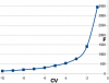
Then you need to convert the control voltage from 1V per octave into a current that doubles for each octave. For example:

CV = 0V --> current = 25 µA
CV = 1V --> current = 50 µA
CV = 2V --> current = 100 µA
CV = 3V --> current = 200 µA
CV = 4V --> current = 400 µA
CV = 5V --> current = 800 µA

The formula for this conversion is: current = 25 µA multiplied by (2 to the power of CV). This is an exponential conversion and a circuit that implements it is called an exponential converter.

I Googled exponential converter circuit and found several designs, and lots of information about exponential converters in music applications:
http://electronicmusic.wikia.com/wiki/Exponential_converter
http://home.comcast.net/~ijfritz/sy_cir7.htm
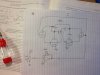
 

Proschuno

Aug 1, 2011
94
Joined
Aug 1, 2011
Messages
94
Apologies, yes, it is being used as a musical synthesizer. No, I am not trying to make a square wave, (using pentodes as the multivibrator makes that very easy), as it actually makes a roughly shaped sawtooth wave on the oscilloscope. Actually, I'm really doing this for the experience more than actually trying to get a "tube sound", so I really don't care what kind of wave form it makes, just as long as I can get a Volt/Octave Frequency response.

I suppose I should have more greatly detailed how I think the circuit works: The 12AU7 is wired up to be a basic multivibrator; the 6SN7 is wired up connecting its plates directly to the 12AU7's plates, then connecting its cathodes to the 12Au7's grids. I'm supposing this shorts some of the current to the 12AU7's grids, thus lessening the charge time, which can be varied by varying the 6SN7's resistance, by varying the voltage at its grids. The voltage applied at the 6sn7's grids is what controls the frequency, which the VCO can actually go about 5-6 octaves depending on the multivibrators resistor and capacitor values.

So I'm wanting to know what would be best to do (If I should; the idea involving the PNP transistor seems better now actually….) to get a Volt/Octave Response by applying a voltage at the 6SN7's grids.

I've redrawn the circuit more legibly also.

And As I've stated the 6SN7 are the triodes on the outside, 12AU7 inside in the drawing.

attachment.php
 

Attachments

  • photo-2.jpg
    photo-2.jpg
    61.1 KB · Views: 407
Last edited by a moderator:

KrisBlueNZ

Sadly passed away in 2015
Nov 28, 2011
8,393
Joined
Nov 28, 2011
Messages
8,393
I'm not sure how your circuit will behave. I can see that when the opposite triode turns ON, the falling anode voltage will be coupled through the capacitor to the grid and the grid will try to go negative, but will be prevented (or at least hampered) by the cathode follower driving the grid. This cathode follower won't be operating properly because its anode isn't tied to HT, but to the anode of the associated triode, where the voltage is rising at a limited rate because of the other capacitor that is coupling it to the opposite grid which will become forward-biased.

So I'm not surprised that you're seeing trianglar waveforms at both anodes. I AM surprised that the grid voltages on the 6SN7 triodes affect the frequency in a linear way though!

If the oscillator frequency is actually linearly proportional to the grid voltage (with some offset, I guess), which I kind of doubt, then to get a one volt per octave response, you need to convert the 1V/octave (logarithmic) control voltage to a second control voltage (or current) that doubles for every octave. This requires an exponential converter, as I said. An increase of 1V at the input of the exponential converter will cause its output voltage (or current) to double.

Do what I did: Google exponential converter circuit and see what your options are.
 

Proschuno

Aug 1, 2011
94
Joined
Aug 1, 2011
Messages
94
I don't know if I explained this earlier or not, but the VCO's frequency already has an exponential response to input voltages on the 6SN7's grids.

Also, I've exhausted most of google already on exponential converters, pouring through people's websites like Rene' Schmitz, Eric Barbour and Ken Stone (synth builders whom have all worked with tubes and expo converters). But I will look again.
 

KrisBlueNZ

Sadly passed away in 2015
Nov 28, 2011
8,393
Joined
Nov 28, 2011
Messages
8,393
If the VCO already has an exponential response to the control voltage at the 6SN7's grids, which I doubt, then all you need is to scale the control voltage so that a 1V change will cause a factor of 2 change in frequency.

Do you have a frequency counter or some other way to measure frequency? (For example, a PC sound card.) If so, measure the frequency at several different control voltages and post the list here.
 

Proschuno

Aug 1, 2011
94
Joined
Aug 1, 2011
Messages
94
Ok, will do. I'll have to set up my circuit again and test, hopefully post the results by tomorrow afternoon.
 

Proschuno

Aug 1, 2011
94
Joined
Aug 1, 2011
Messages
94
Ok so discussing this with another Synth builder via email and remembering some of my former calculations, I believe that this actually has a 1/x response, times a scaling factor. Recording the PERIODS (not frequencies!) of the waveforms I remember that the data plotted a straight line, which obviously involves dividing 1 by the periods to get frequency. I wish I still had the results on my TI83 and I could show you, but I just remembered this just thinking about it (and that I don't feel like re-breadboarding everything again).

I will breadboard this regardless though and record some frequencies.

So I suppose I would build a circuit that gave a 1/x response to an input voltage, then run this to the VCO, which would make the two functions cancel to just give me x, which then it will be linearized (the 'x' multiplied by some factor obviously; 1volt won't correspond to 1Hz of course), by which then I could run an expo converter to the first 1/x converter?

BTW, I am using an oscilloscope, but I hope to be able to afford a frequency counter soon.
 

KrisBlueNZ

Sadly passed away in 2015
Nov 28, 2011
8,393
Joined
Nov 28, 2011
Messages
8,393
In a normal VCO, the control voltage determines the charge (and/or discharge) current fed into the timing capacitor(s). This current is directly proportional to the control voltage. There may also be an offset, but I'll ignore offsets for simplicity.

Take a conventional simple fixed-frequency oscillator made with resistors and capacitors. For simplicity let's say that the capacitor is charged and discharged between two voltage thresholds, and that the charge and discharge current passes through a resistor.

The product of R and C is called t, the time constant of the resistor and capacitor together, and the period of the oscillator's output waveform is related to t by a fixed ratio that depends on the voltage thresholds used, which are constant for a given design.

When the resistor is replaced by a current source and/or sink circuit, in this case a variable one whose current is linearly proportional to the control voltage, the oscillator's cycle time becomes proportional to C divided by the current. In other words, there is a reciprocal relationship between the control voltage and the cycle period.

There is also a reciprocal relationship between the cycle period and the frequency (f=1/t) so there is a linear relationship between the control voltage and the frequency.

So I think your memory may be unclear on this. I would expect a VCO to have a linear relationship between control voltage and frequency, if the control voltage is simply converted into a proportional current that is applied to the capacitor to produce the oscillation.

I wouldn't expect your two-toob design to have a linear frequency vs. control voltage response over any useful range, but I guess it's possible!

If it's true, I think you just need an antilog or exponential converter, with scaling at the input and output.

Does this make sense?
 

Proschuno

Aug 1, 2011
94
Joined
Aug 1, 2011
Messages
94
Yes, it makes perfect sense. And looking over data sheets, there should be a linear ration between current and grid voltage, but I'm not understanding either how it's not, given the results:

-10V ---> 7ms ---> 142.86 Hz
-9V ---> 5.99ms ---> 166.94 Hz
-8V ---> 4.8ms ----> 208.33 Hz
-7V -----> 3.99ms -----> 250.63 Hz
-6V ----> 3.2ms ----> 312.5
-5V ----> 2.4ms ----> 416.67
-4V ---> 1.84ms ---> 543.48
-3V -----> 1.3ms ----> 769.23 Hz
-2V -----> .71ms -----> 1408.5 Hz
-1v ------> .29ms ------> 3448.3 Hz
 
Last edited:

KrisBlueNZ

Sadly passed away in 2015
Nov 28, 2011
8,393
Joined
Nov 28, 2011
Messages
8,393
I've plotted the data you listed. Here's frequency vs. control voltage, plotted on two linear axes.

attachment.php


The data sheet only gives you data for the toob under fixed conditions. In your circuit, the current is changing constantly as the anode voltage changes and as the capacitor charges up. The operating conditions of the toob are changing constantly throughout the oscillator cycle. That's why I said I wouldn't expect it to be linear over any useful range.

In other words, I don't think that design will be usable. Actually I don't think that multivibrator is the best design to use; I would use one with a single timing capacitor. Also I think you'll need a lot more than four active components to make the circuit's frequency vs. control voltage graph linear over any useful range. To try to keep it fully toobular is to fight a losing battle I think.
 

Attachments

  • cv vs frequency.png
    cv vs frequency.png
    10.1 KB · Views: 402

Proschuno

Aug 1, 2011
94
Joined
Aug 1, 2011
Messages
94
I see…. i actually figured that a multivibrator would be hard to use. Could I theoretically use pentodes, and then just vary the screen voltage? wouldn't that vary the current linearly? I've barely messed with pentodes so that's just speculation.

But, after all is said and done, I'm just going to stick with my thyratrons I have (these only take one capacitor and resistor).
 

KrisBlueNZ

Sadly passed away in 2015
Nov 28, 2011
8,393
Joined
Nov 28, 2011
Messages
8,393
I see…. i actually figured that a multivibrator would be hard to use. Could I theoretically use pentodes, and then just vary the screen voltage? wouldn't that vary the current linearly? I've barely messed with pentodes so that's just speculation.
I don't know whether varying the screen grid voltage would vary the current linearly or not, but even if it did, I'm not sure that would help.

If you're planning to replace the 12AU7 with pentodes, it won't help at all, since the current you need to vary is the current with which the capacitors are charged; varying the currents that the oscillator toobs draw through their anode resistors will not work the same way.

If you're planning on replacing the 6SN7 with pentodes, I doubt you'll get any better linearity. The way they're wired, their cathodes are jumping around over a pretty wide voltage range, and the grid voltage is referred to the cathode. That's why the capacitor charge current won't be constant, and why you won't see linear behaviour.

I'm not experienced enough with toobs to be able to be any more specific than that, I'm afraid.

But, after all is said and done, I'm just going to stick with my thyratrons I have (these only take one capacitor and resistor).
Sounds like a plan :)
 
Top