Al Slitter
- Nov 4, 2016
- 41
- Joined
- Nov 4, 2016
- Messages
- 41
Hello All;
I have an issue that I would like confirmation on, I have built a couple of emergency lights.
The layout is very simple consisting of a 18650 battery, a single battery holder, an on-off switch
a resister and 3 - 3Watt LED's wired in parallel.
I will charge the batteries after use using my 4-battery independent charger.
These leave me with one issue outstanding and that is the installation of a 1S BMS (Battery Management System). I purchase several of these boards and wired them up, the next test was to
verify that the 1S board would actually shut the light off when the voltage became low,
This test ended in failure so here I am trying to figure out why.
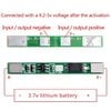
I wired the + / - battery poles to the areas marked B+ and B- as shown in the image below.
I then wired the leads to the LED's to P+ and P-.
As mentioned there was not charging leads needed to be installed as the charging of the batteries will be a manual process.
Has anyone got an idea where I went wrong?
Thanks in advance.
I am including an image of this board:
I have an issue that I would like confirmation on, I have built a couple of emergency lights.
The layout is very simple consisting of a 18650 battery, a single battery holder, an on-off switch
a resister and 3 - 3Watt LED's wired in parallel.
I will charge the batteries after use using my 4-battery independent charger.
These leave me with one issue outstanding and that is the installation of a 1S BMS (Battery Management System). I purchase several of these boards and wired them up, the next test was to
verify that the 1S board would actually shut the light off when the voltage became low,
This test ended in failure so here I am trying to figure out why.
I wired the + / - battery poles to the areas marked B+ and B- as shown in the image below.
I then wired the leads to the LED's to P+ and P-.
As mentioned there was not charging leads needed to be installed as the charging of the batteries will be a manual process.
Has anyone got an idea where I went wrong?
Thanks in advance.
I am including an image of this board: