Maker Pro
Maker Pro

Are there any alternative to epson ic A2098, C6082?

ngzek

Aug 4, 2015
26
Joined
Aug 4, 2015
Messages
26
I found Epson printer ic A2098 and C6082 were shorted.These ic are not found in the market. Is there any alternative ic to replce these Epson ic? Please help
 

davenn

Moderator
Sep 5, 2009
14,260
Joined
Sep 5, 2009
Messages
14,260
without knowing what their purpose is ... no one could help

but they are probably purpose designed, so highly unlikely anyway
 

73's de Edd

Aug 21, 2015
3,622
Joined
Aug 21, 2015
Messages
3,622
.

Sir ngzek . . . . .


It would be nice for you to have given the model of the Epson printer to research.
Strange that you are assuming the devics to be integrated circuits
I am suspecting them just to be common bipolar power transistors.
Those numbers are akin to the common assigment used for foreign transistors.
There are certainly HUGE (to the power of 10) quantities of smaller cased small signal transistors
coming off of production lines daily.
And almost from day one, there was a problem in getting a part number on small cases.
Be it by the use of printing via ink or intermediate times by the use of acid etch or todays time of
use of a laser to burn the markings on.
There was MINIMAL area to print info on the case, so it took no time at all to see that there were
the familys of 2SA-2SB-2SC-2SD-2SK identifiers, with the REAL info being in the 3rd character ID
and the numbers to follow. SO . . . . since the 2S was always being redundant on ALL of the families,
so why not just OMIT it.

So that is what I almost universally see as being done on that family of foreign transistors.
The most common used transistors I usually see, are merely marked with the short form of A733 or C945
which marks on the transistors cases much easier than the transistors FULL IDENTIFIER of 2SA733 or 2SC945.

In your case the A2098 and C6082 would be fully identified as 2SA2098 and 2SC6082.
In which case if you reference their specs:

The 2SA2098 is going to be a silicon PNP bipolar power transistor with a 30 watt rating @ 60V and
15 Max amps and a gain of 180 with a Ft of 200Mhz (of which that last spec should be of no relevance
on use in a printer.) and a casing in a TO220ML profile.

The 2SC6082 is going to be a silicon NPN bipolar power transistor with a 25 watt rating @ 60V and 15
Max amps and a MINIMUM gain of 50 with a Ft of 195Mhz (of which that last spec should be of no relevance
on use in a printer.) and a casing in a TO220ML profile.

They are almost being a NPN and PNP matching set.

Here are URL's for getting ALL of their specs:

http://alltransistors.com/transistor.php?transistor=56652
http://alltransistors.com/transistor.php?transistor=49602


73's de Edd
 

davenn

Moderator
Sep 5, 2009
14,260
Joined
Sep 5, 2009
Messages
14,260
a couple of sharp and well lit pic's of the devices would confirm if they are ICs or transistors
 

ngzek

Aug 4, 2015
26
Joined
Aug 4, 2015
Messages
26
Printer model is epson1390
 

Attachments

  • NGA.jpg
    NGA.jpg
    44.2 KB · Views: 515

davenn

Moderator
Sep 5, 2009
14,260
Joined
Sep 5, 2009
Messages
14,260
yeah OK ... so they are transistors as Edd suggested

2SC6082 and 2SA2098
They or their equivalents should be readily available

the unknown is a temperature sensor .... most likely a diode or a thermistor


Dave
 

ngzek

Aug 4, 2015
26
Joined
Aug 4, 2015
Messages
26
Davenn temperature sensor! Ok thanks for your help.
 

ngzek

Aug 4, 2015
26
Joined
Aug 4, 2015
Messages
26
I don't know why this manufacturer mention nothing about it? Its a trouble for some people like me. Yes you are right Davenn it is screwed to heatsink.
 

73's de Edd

Aug 21, 2015
3,622
Joined
Aug 21, 2015
Messages
3,622
Sir ngzek . . . . .


By using your forthcoming model number of the Epson unit:

And then with my further REALLY-searching of the unit, reveals that two complementary sets of those given transistors are used to send
precise timed HIGH current pulses to the units’ printer heads.


Sooooooo . . . . I don't know if you spent a bunch of your HARD earned munneys on that unit, when being new or were merely "gifted" of
one of the units . . . . but with it being inoperative.


With ALL of the motors that unit is using, I might have easily suspicioned some few power transistors additionally feeding/ switching power
to them.


But . . . no . . . there are just two tandem sets of the complementary units, designated as Q6-Q9 and Q10-11.

REFERENCING:


You can get a free service manual of the 3900 unit at:

http://elektrotanya.com/epson_stylus_photo_1390_1400_1410.pdf/download.html

Newbie to that site? ? ? ? ?

(WAIT until the fine little print of all the massive contractual info displayed at the left bottom/central corner area exhibits a change from having
its few words of underlined "Please wait, processing" makes a transition, to instead, its saying "Get manual", then you place the mouse
cursor/pointer atop that area.


And then . . . .AND THEN . . .you keep rolling your chair as FAR back away from the computer keyboard as you POSSIBLY can, and then extend
your right arm and its end index finger out as FAR as it will possibly reach and then BARELY be able to reach to the mouse’s left tact switch .
Then you dub'l click it and run like HELL, as we certainly don't know WHAT is going to happen next!


With manual, then downloaded, you will find its troubleshooting's relevant schematics within its last few final pages, just prior to #168.

TROUBLESHOOTING:


Specifically . . . I have placed a separate small snippet of that most relevant schema info with this post, just below, with the CN10 CN11 CN12
connector cables pinouts of the printer head also being included.


My "markups" are being made in PINK, along with some BLUE and GREEN paths of the high current drive levels to the printer heads.

Initially we see that the top left block diagram shows the power supply info, with my entries in PINK that feeds to the main board of the unit..

Dropping down to the right center of the schematic, we see that the two sets of power transistors are used in totem-pole fashion and pass out
their HIGH current trapezoidal drive pulses as the BLUE and GREEN feed lines. They are interconnects with the CN 10-11-12 terminals and then
route to the printer head(s).


There is DIRECT Emitter to Collector connectivity of the series transistors, with NO resistive current limiters inline, so those lines are going to hit
that printer hard as heck.


(Limited only by the feedback sample sent back to IC 10 via those broken BLUE and GREEN lines feeding back to its pins 12 and 18


As for your "mystery device" photo (for Thermal sensing ? )

By the schematic page below, as it’s far right referencing, you can see that the most common look alike manufacturer’s symbol trade logos don't
quite match up with yours, with the closest being the Signetics, if being right sloped to an italic type of font and having a folding around of the S ends.


I am not finding it showing up in the close proximity of your power transistor cluster, with all of the ancillary resistors on the schematic around them,
just being mere 1/4 watt rated units, associated with establishing proper base drive biasing, from their incoming timing data pulses from IC10 pins
11- 13-17 and 19. Then a couple of H.F. R/C snubbers dropping off those BLUE and GREEN lines to ground as R159/C128 and R164/C129.


Sooooooo . . . . you might just have to check out where that unit was physically wired into and mechanically located / mounted to , when being compared
against the schematic.


There IS being feedback sent from the printer head(s), of the units’ thermal situation, via pin 1 of the CN 10 connector which is labeled as TH, so you just
might see if that line leads to the device you have pulled if it was located on the print head assembly heat sinking.


(My markup is the PINK star at that CN 10's connector pin 1.)

How does that unit test, either resistance wise and /or as a semiconductor with its directional conductance characteristics?

ALSO how did the two bipolar power semis check out, as per any "fried” or open junctions?

EVALUATING:


A shakedown test might involve the unit being in power down condition and measuring the resistance being on the BLUE and GREEN drive lines, considering
that the pair of transistors that were NOT affected by meltdown are probably still tied into a valid printer head, while the other crashed semis were connected to
a printer head that has shorted down windings or a shorted winding to frame condition / failure.


AN ASIDE OBSERVATION:


Looks like it will be up to you for finding the wiring within the print heads or connecting motors, as they are considered replacement units and their specific sub
assembly wiring is not shown for tracing or troubleshooting.


If you don't find a "burnt" out / shorted printer head, you might just luck out in getting the unit up and functional again.

HOWEVER finding involved mechanical and / or any software related problems just might then prove to be a killer of your hopes.

To wit . . . on manual page 137 . . . do take note of their special dedicated test instrument, which utilizes an input from a goose neck mounted electret mike for its
picking up the "pluck"/frequency of a timing belt for the proper setting of its tensioning.


(Akin to tuning a guitar string.)

Thassssittt . . . . . update us of your findings, info or further queries.


Behold ! . . . . . al fin . . . . . le schematique:

<img src="http://s24.postimg.org/paazslis3/Servicing_an_Epson_1390_Printer.png" class="bbCodeImage LbImage" alt="[&#x200B;IMG]" data-url="
Servicing_an_Epson_1390_Printer.png
">


Alternate hosting of the schematic . . .but if coming up to small, it may need to be mouse clicked upon.
http://s24.postimg.org/paazslis3/Servicing_an_Epson_1390_Printer.png


73’s de Edd


.
 

ngzek

Aug 4, 2015
26
Joined
Aug 4, 2015
Messages
26
Sir 73’s de Edd you are very helpful and I have learn lots from you. Thank you
 

Mbaltay

Mar 25, 2022
4
Joined
Mar 25, 2022
Messages
4
Sir 73's fe Edd,

If you still have your marked up schematic, can you please repost or send it? I have the original, but looking for your marks.

I have a similar model Epson that I'm trying to troubleshoot, and then possibly modify.

Thanks alot,
Mike

[mod edit: added notification for Edd] @73's de Edd : here's a question to a 7 year old thread for you ;)
 
Last edited by a moderator:

73's de Edd

Aug 21, 2015
3,622
Joined
Aug 21, 2015
Messages
3,622
Sir Mbaltay . . . . .

Wel . .l . .l . .l . . l . . . first-est . . .of all . . . .are you the original owner of this unit as its user, from day one 2006'ish thru 2022 ?
OR . . . are you its thrift store / gifted or curbside find recipient ?
Since that unit has software that times out and shuts it down from its digital signal of the print head drives after a prescribed use and the concurrent filling up of its ink pad "kotexes". In the lapsed usable time frame it should have shut down about 3 times . . .2006---2021 until they were replaced and software reset..
My schematic has lapsed its hosting time limit and this site did not save it either. I also think it was on one of 45 of my flash drives . . . . couldn't find it by that title.
I will start another . . . . with the printer drive markups and extra info.
The note in GREY on the pads,at the bottom of the page.
The schemas point of interest at top, and the flow of the trapezoidal drive signals from the two sets of complementary power driver transistors.
Print heads relevant connectors and their related connections functions.
Confirm you have all supply voltages.
SCHEMATIC SNIPPET . . . . .
upload_2022-3-28_17-11-12.png

73's de Edd . . . . .

upload_2022-3-28_17-17-50.png

.


Mbaltay

Mar 25, 2022
4
Joined
Mar 25, 2022
Messages
4
Sir Edd,

Thank you very much for your reply and for regenerating that schematique. I am most grateful. Your previous post sent me definitely in the right direction. I have learned much more since my initial post.

CONTEXT
The printer in question is an Epson L1800 modifed with a flatbed stepper stage assembly. I bought it new late last year to print very thin flex circuits for the startup I am building. We have developed a very simple elegant way to measure neural activity deep in the brainstem by recording oculomotor activity using a piezo electric strain gauge. I started at the USDOE at one of our national labs supporting basic research in particle physics. The work I am doing now is in part supported by a phase II SBIR grant through the NSF. We always are very thin on resources, so I super appreciate any and all help from experienced pros like yourself.

Please let me know if you would like me to share more of what I know and have learned about this printer, Epson technology, jetting viscous silver conducting inks or the overall subjects of producing thin film piezoelectric sensors and brainstem neuroscience.

IMMEDIATE AIMS
I very much would like to get my board and printer back up and running after I accidentally shorted the ribbon cable that runs between the main board to the print head (CN12 see below), and then more importantly to overdrive the print head for our specific use of the printer. (if possible).

EPSON L1800 PRINTER
The L1800 belongs to a broader class of A3 format high resolution printers that I believe all use the same third generation micropiezo print head model. These include the 1390, 1400, 1410, 1430 1500W plus some other RX and odd models. Within the group, aside from common printhead, the boards and operation are parsed by the ink configuration (ecotank/CISS vs cartridge format) and other options peripheral to the core print engine. The L1800 is an Ecotank model which uses refillable ink reservoirs. Ecotanks use the same waste ink diaper as many other epsons but do not enjoy those splendid maintenance features relating to cartridge changeouts. Rather prompt the user to refill the cartridges predominantly based on some Japanese algebra, but in no way upon any ink level sensors or any other fluidic input. Modifiers like us simply route the waste ink line into a high precision after-market receptacle, namely an empty plastic shampoo bottle and download the reset program that is now widely available for free.
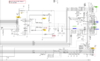
LE SCHEMATIQUES
I have attached below the closest schematic that I can find an Epson L1800 printer. I looked exhaustively with no luck. One document below is the main board and print head excerpted from a service manual similar to that one you shared. The other single page is a close up of the print head driving section. The main difference between the board and circuits of our L1800 and the schematic that I have posted here seems to relate to the ink cartridge lockouts. The entire printhead driving section seems to match closely with my reality except that the L1800 board uses different PNP transistors. L1800 uses A2210 while the NPNs are the same C6082s. I pulled datasheets and suspect both are made by Sanyo. The component and CN numbers differ between attached and my L1800 board. I will use the names from the schematic for ease.

Turning now to MY (first) FRIED BOARD SITUATION…
Troubles initiated with my shorting ribbon cable of CN12 with a razor blade, which in turn blew F2, one CH of the amplifier (2/4 transistors), and maybe IC10. At the time CN12, 13 and 14 were disconnected but, in one of those moments of sheer stupidity, 42V power was live on this main board.

After I replaced F2 and the two bad transistors, the system powered up and ran normally EXCEPT no piezo jetting - no ink. According to many online posts, this is common. Users short their main board upon clean the printhead (and ribbon cable ends) with fluids. It is common to have these symptoms or no power after fluid cleaning when some combination of F2, Qs and or IC10 are damaged. After replacing F2, trannys and maybe IC10, most users report either: a., problem solved, or b. immediate reoccurence of blown main board components, due to the fact that one or more printhead circuits are shorted which in turn repeatedly shorts main board.
So I replaced IC10 with a chip of same part number but unknown condition from a parts machine. Still I get no jetting but system runs otherwise normally.

I confirmed DC power, both 3.3 and 42 V is present at all required points (except at CN15, which I believe is not needed for my printer model). I confirmed no obvious shorts or loss of continuity. Pulled and measured 3 caps which seem good although dissipation is out of spec on one. Generally the board seems functional and repaired. Pins on IC10 seem normal. Transistor pins ohm out as expected. I did have to repair two lost traces including a wired connection from Q6 pin2 C to Q10 pin 2 C and another on pin 4 of IC10.

So what could be the cause of no piezo jetting?
I verified that the printhead (PH) is not clogged and that it does not seem to be shorted. The PH was disconnected at the instance of my initial shorting of the cable. The PH ohms out fine. Transistors and F2 do not refail when I reoperate the printer after replacing board components. I have a new PH on order. I have not dug into those electronics, but there is one schematic in the attached schematics.

Using a Fluke digital scopemeter, I attempted to measure input and output signals to the amplifier. I connected the whole system to the printer and executed a steady print command while measuring values.

DC bias was about 1.6VDC between the base of Q6 and GND, good I think.

There are output pulses between COMA-1 and GND, measured at pin 3 E of Q6. Pulses seem to arise when the head is supposed to be printing and they are spaced about 10- 20 uSec apart maybe. They are about 7.5 V peak, maybe 10 uSec or so wide only positive. There are occasions where the amplitude and pattern seem to shift and auto amplitude goes up in sensitivity. Maybe pulses are off during a carriage return or movement. Pulses seem to turn on prior to necessity and dwell for a while after printing stops.

I saw the same pattern on all 4 transistors. The waveform was not inverted, but I had the scopemeter on automatic and cannot be sure, or even if they should be.

I tried to measure input to Q6 between base and GND, but it seems I measure the same waveform as above again.

HOW TO BE AN IDIOT TWICE IN ONE WEEK….
I was preparing to dig further into more systematic testing when I accidentally shorted Q6 with the tip of my probe…. F2 blown, 2 of 4 transistors blown again. I am trying to source a known good IC10, but it seems very hard to find so I am picking up another printer that works and uses same chip. Good thing the little guy in my gut told me to buy extra fuses and transistors. I guess experience can partially offset idiocy. I retested the print head which this time was connected, but it seems ok.

It is possible that there is some sort of software or lockout present. Just about the time this all occurred before first short, there was a warning message that the waste ink was 99% full so I downloaded the program and reset its counter. The lockout and msg. ceased. So this makes me believe that if it were some lockout causing the no piezo action then I would see some error msg. Also, the Epson Adjustment program allows me to interrogate the entirety and each major sub-system and all systems report "ready to print". That said, there are a number of "enable" signals of which I do not quite know how to test.

I have cleaned up the board, rebuilt traces and will solder it back together maybe Wednesday when I get the parts. It may work, but I am dubious… The only place to get a replacement (genuine or otherwise) is Hong Kong or Shenzen.

I hope to get it going so that I can work on the real challenge which is jetting viscous conductive silver inks, which may well benefit from increased piezo voltage..

Best and Thanks

Mike
 

Attachments

  • Epson Artisan 1340 L1800 Look Alike.PNG
    Epson Artisan 1340 L1800 Look Alike.PNG
    528.5 KB · Views: 14
  • 1410-1500 Schematics.pdf
    978.6 KB · Views: 15

Mbaltay

Mar 25, 2022
4
Joined
Mar 25, 2022
Messages
4
Hello,

Just a quick update. Thursday I rebuilt the main board with new and used components including a used but reportedly good printhead and driver chip. I checked all the main pathways around the printhead driver circuits and they all seem correct. The board is not pretty after pulling it apart a few times, but the basic traces, R,C,Q and fuse all seem functional DC rails good and the driver chip does not seem to be shorted.

..so with great hopes I power it up and everything operates normally, great, so I send a print job, stand back and pray- NOPE No ink No answer from the printer gods. The beast still acts and moves 100% as if it should be printing, but no ink is being ejected out of its nozzles. Today I plan to do a bit more systematic testing looking at the signal using scopemeter, but I am beginning to think either I put in a bad driver chip, or that the main chip is messed up and not sending the correct signals. It is difficult to actually test the driver chip because I source it from used printers that usually are out of ink, and therefore cannot test print. I guess I could go out and buy six Epson ink cartridges just so I can power up an old printer, but that seems counterintuitive. Also, I am worried about the pads lifting below that chip if I keep replacing it. I have not ruled out any possibilities yet, but I am starting to get that feeling I get before throwing in the towel. My hope is that someone with much more experience than I will have some smart advice.

Thanks again to anyone who is reading this.

Best,
Mike
 

Mbaltay

Mar 25, 2022
4
Joined
Mar 25, 2022
Messages
4
Hello all-

Please advise if I should create a new post. I have resolved my board issues and am now ready for the second phase which is to figure out if there is a relatively easy way to overdrive this piezo inkhead.

The schematics are quite accurate in regards to the basic amplifier and waveform generator.

Can anyone suggest a way to increase the power or amplitude to the generated waveform without blowing something else in the system?

Could it be as simple as adjusting the feedback resistance ratio?

Best,
Mike
 

10100rsn

Jul 24, 2022
1
Joined
Jul 24, 2022
Messages
1
Hello all-

Please advise if I should create a new post. I have resolved my board issues and am now ready for the second phase which is to figure out if there is a relatively easy way to overdrive this piezo inkhead.

The schematics are quite accurate in regards to the basic amplifier and waveform generator.

Can anyone suggest a way to increase the power or amplitude to the generated waveform without blowing something else in the system?

Could it be as simple as adjusting the feedback resistance ratio?

Best,
Mike
Hi Mbaltay. I was curious, what finally solved your board issues? I have to run through the same gauntlet it seems and was just curious what finally fixed it for you.

Also, why increase the amplitude of the amplifier? Are you trying to pump ink through the paper? ;P
 
Top