Hi
I'm having a bit of a problem with a project I'm working on that consist of a Arduino chip(ATMegA 328p), mosfets and RGB strip(1m).
I also built a power supply with an output of 12v and 5v to power the RGB strip and Arduino chip using a transformer with split secondary coils(17v-0v-17v) with 2Amp rating.
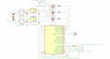
(attached you will find and shematic of the whole circuit.)
The power supply is working fully powering the arduino and RGB strip just fine.
The MAIN PROBLEM I've been struggling for days is that when my arduino chip pulses the gate of the mosfets it opens up the gate and switches the rgb strip on ,but the strip wont change color as i anticipated and if i remove the chips output pin from the gate the specific color still stays on even thou there is nothing connected to the gate.
I've done extensive research and still could not get it right.
(attached you will find the mosfets I've used datasheets)
main goal of the project is to be able to control the strip through bluetooth via module that is addd to the chip but i cant move on before the rgb strip can successfully change color.
IM also busy designing PCB so i cant get it printed before everything isnt working fully on breadboard
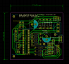
(attached you will find PCB schematic)


ANY HELP WOULD BE APPRECIATED!
PS. Keep in mind this is one of my first projects")
im still a noob.
I'm having a bit of a problem with a project I'm working on that consist of a Arduino chip(ATMegA 328p), mosfets and RGB strip(1m).
I also built a power supply with an output of 12v and 5v to power the RGB strip and Arduino chip using a transformer with split secondary coils(17v-0v-17v) with 2Amp rating.
(attached you will find and shematic of the whole circuit.)
The power supply is working fully powering the arduino and RGB strip just fine.
The MAIN PROBLEM I've been struggling for days is that when my arduino chip pulses the gate of the mosfets it opens up the gate and switches the rgb strip on ,but the strip wont change color as i anticipated and if i remove the chips output pin from the gate the specific color still stays on even thou there is nothing connected to the gate.
I've done extensive research and still could not get it right.
(attached you will find the mosfets I've used datasheets)
main goal of the project is to be able to control the strip through bluetooth via module that is addd to the chip but i cant move on before the rgb strip can successfully change color.
IM also busy designing PCB so i cant get it printed before everything isnt working fully on breadboard
(attached you will find PCB schematic)
ANY HELP WOULD BE APPRECIATED!
PS. Keep in mind this is one of my first projects
im still a noob.
Attachments
-
 Shematic.png50.2 KB · Views: 279
 -
irl3705n.pdf111.9 KB · Views: 37
-
IRFZ44N Datasheet.pdf67.5 KB · Views: 41
-
IRL3705N datasheet.pdf111.9 KB · Views: 49
-
 Shematic.png50.2 KB · Views: 125
 -
 pcb.png66.4 KB · Views: 118
 -
IRL3705N datasheet.pdf111.9 KB · Views: 43
-
IRFZ44N Datasheet.pdf67.5 KB · Views: 35