Maker Pro
Maker Pro

Another treadmill problem

loungedebaldy

Nov 28, 2013
45
Joined
Nov 28, 2013
Messages
45
Hi everyone! This is my first post in the forum and I would like to ask for your help in this project. I know little about electronics but would sure like to learn more and would appreciate and thank you in advance for your inputs. Also, this treadmill belongs to my 80 year old father in law and it would greatly improve our relationship if I could fix this thing for him. I can see that there have been quite a few questions concerning treadmill repair and I am sure you are tired of them but hope you can help me.

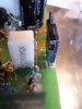
With all that being said here is essentially the problem as I can understand it. Basically, the motor won't run or turn. The treadmill is a Tempo Fitness Model 611T and was purchased new in 2010. I see the circuit board that the motor is plugged into says Johnsonfitness. I will try post a few pics here. I assume that this board is the motor control board seeing that the motor is plugged into it. I don't know what number it would be and have no reverse side pic of it at this time but will sure try to get more pics if needed

When the speed is set and the start button pressed the inclination motor will go up to the end and then an error message shows on the display but the motor doesn't start. Again if you press the start button the inclination motor will start and go down or the other way and come to a stop and again the error message but no drive motor start.

I called the service support and after their instructions used a portable drill battery to see if the motor turned and it did. They said that the board was faulty and wanted to send a new one for only $200.00. That was not an option for obvious reasons so here I am.

If I cannot get it working back to normal he would be happy to just get the motor to turn in someway that he could control the speed and thus be able to use it without the bells and whistles.
Thanks for any help.
Baldy
.
 

davenn

Moderator
Sep 5, 2009
14,260
Joined
Sep 5, 2009
Messages
14,260
hi
welcome to the forums :)

OK so from your test we will currently assume the motor is fine
You need to work out how the motor is controlled by the board
determine the output from the board that drives the motor measure voltages at those points ....
is the motor low voltage DC or AC or is it switched mains voltage supply ?
You need to determine that so as not to risk getting electrocuted

Post photos of the board ... both sides sharp and well lit
look at your pics before you post them .... if you cant read values on the components ... nor will we be able to keep your pics to a max of ~ 800 x 600 and ~ 100kb

cheers
Dave
 

loungedebaldy

Nov 28, 2013
45
Joined
Nov 28, 2013
Messages
45
Hi Dave and thanks for the warm welcome. I will have to go and see if I can get some readings and information for you and more pics and figure how to send some pics.
Baldy
 

loungedebaldy

Nov 28, 2013
45
Joined
Nov 28, 2013
Messages
45
Finally back and hopefully can send some pics. I did try to take a reading at the outputs for the motor but there was no reading when the mill was started. We took the control display panel off and looked at that board and will post a pic. All the buttons on that board worked and no obvious burn colors. The motor is a DC motor 90v. 1.25 hp. As far as how it is driven, I will have to have a better look. Would there be a schematic of that board available? How do you trace the circuit? I did notice when looking at the pics that the red and blk motor wires were put backward on the board when we put things back and tested to see if it was working. Would that just make the motor turn backward? OK, will send this and see what you think. Thanks\Baldy:)
 

Attachments

  • new pics of treadmill boards 2013-11-29 002 (800x600) (640x480).jpg
    new pics of treadmill boards 2013-11-29 002 (800x600) (640x480).jpg
    31.6 KB · Views: 371
  • new pics of treadmill boards 2013-11-29 003 (800x600) (640x480).jpg
    new pics of treadmill boards 2013-11-29 003 (800x600) (640x480).jpg
    58.7 KB · Views: 695
  • new pics of treadmill boards 2013-11-29 004 (800x600) (640x480).jpg
    new pics of treadmill boards 2013-11-29 004 (800x600) (640x480).jpg
    48.2 KB · Views: 645
  • new pics of treadmill boards 2013-11-29 006 (800x600) (640x480).jpg
    new pics of treadmill boards 2013-11-29 006 (800x600) (640x480).jpg
    59.8 KB · Views: 359
  • new pics of treadmill boards 2013-11-29 011 (800x600) (640x480).jpg
    new pics of treadmill boards 2013-11-29 011 (800x600) (640x480).jpg
    54.6 KB · Views: 426

KrisBlueNZ

Sadly passed away in 2015
Nov 28, 2011
8,393
Joined
Nov 28, 2011
Messages
8,393
Yes, a DC motor will turn backwards if the wires to it are reversed.

The wires get in the way of seeing the board properly. Can you upload some pictures of the top side of the board with all the wires disconnected? Also, can you mark up the pictures to show where the motor connects, and where the incoming power connects?

Can you post the markings on the three integrated circuits on the underside? Also, on the top side, can you look for all of the components that are mounted onto aluminium heatsinks, and add the markings to the mark-up on the top side photo(s).

All of that will be very useful to help us understand the design. We will probably need to ask for more details but that should give us a starting point.
 

loungedebaldy

Nov 28, 2013
45
Joined
Nov 28, 2013
Messages
45
OK, Kris. I will try to do that in the next few days. Perhaps by tomorrow evening our time. The mill is a few miles away so it makes it a little unhandy. Thanks for your reply.
Till then..
 

loungedebaldy

Nov 28, 2013
45
Joined
Nov 28, 2013
Messages
45
display board back.jpg

display board front.jpg

main baord 5.jpg

main board 4.jpg

main board 3.jpg

main board 6.jpg

main board.jpgHi, I'm back. Hopefully these pics will turn out and you can see them clearly. I didn't know how to draw circles so I labeled them best I could. This is a good excersize in using a photo program:eek: Let me know if you need more because I brought the board home and can take more pics as needed. Cheers.
 

loungedebaldy

Nov 28, 2013
45
Joined
Nov 28, 2013
Messages
45
Opps! Noticed one pic missing.:D
 

Attachments

  • lower control board back.jpg
    lower control board back.jpg
    61.1 KB · Views: 267

KrisBlueNZ

Sadly passed away in 2015
Nov 28, 2011
8,393
Joined
Nov 28, 2011
Messages
8,393
OK, that's a good start.

It looks like the AC mains supply is rectified by the MP3510S bridge rectifier on the heatsink, and smoothed by the two large electrolytics, then fed to the motor with two or three components in series.

We need to find out more about these components. There seem to be two of them mounted against the heatsink towards the other end from the MP3510S.

In the third picture in post #7 the interesting component is mounted against the heatsink with an aluminium bracket screwed against it. Can you remove the bracket and photograph the front of that component and/or post the markings on it, then replace the bracket.

Also can you post the markings on the large white vertical resistor that's just above it in that photo.

Can you post a closeup of the underside of the board in the area that includes the device with the aluminium bracket against it, and the connections to the vertical circuit board module.

I would also like to see some better photos of the top side of the board. Can you take a photo looking downwards on the board, but slightly angled towards the parts on the heatsink.

Is there another component on the heatsink in between the one with the bracket and the MP3510S at the other end? If so, what are the markings on it?

Do you have a multimeter? If so, measure the resistance of the rectangular white resistor I mentioned.
 

loungedebaldy

Nov 28, 2013
45
Joined
Nov 28, 2013
Messages
45
Hi Kris. I hope I have all the info you asked for and a few pics as well.
Numbers are tiny and not too clear on the two components on board that are attached to the heat sink. The larger one is IRFR250R
Iv R017P the v ls an arrow pointing down
T2 DG

The smaller one to the left is F 1A13AV The F here might be manufacturer
F30U60ST

The number on the white resistor isN5W00021J and read about 7 on the 200 scale of the digital multimeter that I have.
I will post a few more pics for you as well. Thanks
 

Attachments

  • latest pics of treadmill board 2013-12-03 001 (640x480).jpg
    latest pics of treadmill board 2013-12-03 001 (640x480).jpg
    33.5 KB · Views: 250
  • latest pics of treadmill board 2013-12-03 002 (480x640).jpg
    latest pics of treadmill board 2013-12-03 002 (480x640).jpg
    35.4 KB · Views: 344
  • latest pics of treadmill board 2013-12-03 003 (640x480).jpg
    latest pics of treadmill board 2013-12-03 003 (640x480).jpg
    49 KB · Views: 304

KrisBlueNZ

Sadly passed away in 2015
Nov 28, 2011
8,393
Joined
Nov 28, 2011
Messages
8,393
OK. Here's what I've figured out so far. Don't worry about any words you don't understand; this is mainly for my own reference!

Mains is bridge rectified and smoothed by two 560 µF electrolytics, to provide DC to the treadmill motor (90V DC motor).

The motor is controlled using PWM, switched by Q3, an IRFR250R N-channel MOSFET (presumably; see below). D4, a Fairchild FFPF30U60ST 30A fast recovery diode, is connected across the motor. A 5W 0.021 ohm ceramic resistor is connected in the MOSFET's source path for current sensing.

The MOSFET is controlled by the vertically mounted daughter board, which also monitors the source voltage. The whole circuit is at half mains potential.

The full part number of the MOSFET, IRFR250R, is not listed anywhere, but it could be a TO-247-packaged version of an IRF250 (TO-3) or it could be an IRFP250 (M or N suffix, both are identical), which is rated for 200V, 30A, 0.075 ohms at Vgs=10V, 214W dissipation at 25 degrees C.


OK. First, the big vertical white resistor. If you look closely at the markings you'll see that one of the characters is an omega symbol, which means ohms. So the value is 0.021 ohms, and the J letter means 5% tolerance, so the value can vary by up to 5% above or below the stated value.

It looks like it's open-circuit. It should measure much less than 1 ohm but you said it measures about 7 ohms. So you will have to replace it. Unfortunately, 0.021 ohms is not a standard value and suitable 0.021 ohm resistors are not available from Digikey and Mouser, two large mail-order electronic supply companies.

So the next option is to make one, using a number of higher value resistors in parallel. The formula for resistors in parallel is:

Rtotal = 1 / (1/R1 + 1/R2 + 1/R3 ...)

Ten 0.22 ohm 5% resistors (http://www.digikey.com/product-detail/en/1622600-1/A105965CT-ND/3477547) in parallel gives a combined resistance of 0.022 ohms; another resistor is needed in parallel to reduce this to 0.021 ohms. With 10x 0.22 ohms and 1x 0.47 ohms (http://www.digikey.com/product-detail/en/1622603-1/A105967CT-ND/3477550), the total resistance is 0.021016 ohms, with 5% tolerance.

Another option would be twelve of these 0.25 ohm, 1% resistors: http://www.digikey.com/product-detail/en/WHAR25FET/WHAR25FECT-ND/678942 which gives a total resistance of 0.02083 ohms with 1% tolerance.

Squeezing 11 or 12 resistors into that space will be a bit difficult, and untidy, but it's probably the best option.

Second, we need to check Q3 and D4. If either of them has failed, that would cause the resistor to fail. Looking at Q3 front-on, can you measure resistance with the positive probe to the middle lead and the negative probe to the right lead. And can you set your multimeter to the diode test range, if it has one, and measure across D4 in both directions. Post the results.
 

(*steve*)

¡sǝpodᴉʇuɐ ǝɥʇ ɹɐǝɥd
Moderator
Jan 21, 2010
25,510
Joined
Jan 21, 2010
Messages
25,510
Squeezing 11 or 12 resistors into that space will be a bit difficult, and untidy, but it's probably the best option.

Resistors are much cheaper than your time. Buy enough to make at least two of these bodgy resistors in case one starts to smoke as soon as you replace it.

Kris also notes other things to look at, and I'm sure he will make sure you check them before you apply power.
 

KrisBlueNZ

Sadly passed away in 2015
Nov 28, 2011
8,393
Joined
Nov 28, 2011
Messages
8,393
Good idea Steve.

Yes, he needs to check the MOSFET and the diode before applying power; I didn't say this explicitly but I said that if they were faulty, they could have caused the resistor to fail. I assumed he would grok the implications of that!
 

loungedebaldy

Nov 28, 2013
45
Joined
Nov 28, 2013
Messages
45
Wow! Thanks guys. I'm going to check that resistor reading again. I have 2 multimeters. One is an old cheap analogue with needle and the other is a newer, also cheap, digital. Not sure if either can test a diode but will do some checking and if not will try find one that will. Also might add that there was no reading on the other scales only the 200 one and it jumped around from about 5 to 10.5 so kind of averaged it out.:D Hope that jumping around doesn't indicate a problem with the multimeter?
Thanks for the info about applying power. I will not do that until I get further direction from you guys. I may have to get some better meters and will be close to stores on the weekend. It's snowing here and heading for the -20's C on the weekend and I'm heading for Winterpeg.:eek:
 

loungedebaldy

Nov 28, 2013
45
Joined
Nov 28, 2013
Messages
45
OK, I did some more checking and editing of aging eyesight and here is what I have found out. The readings on the analogue multimeter was 1.2 ohms and the digital was 0.4 ohms and was steady and consistent over a number of tries. Don't know why it was jumping around yesterday and why I got a different reading today.:eek: Sorry!
Also, I double checked the number of the MOSFET and it is IRFP250N. Might be why you couldn't find it. Magnifying lenses in combo with reading glasses and a good strong led light showed the numbers and letters quite nicely. I'll check those resistances you asked for on Q3 and D4 and return.
 

KrisBlueNZ

Sadly passed away in 2015
Nov 28, 2011
8,393
Joined
Nov 28, 2011
Messages
8,393
Stick with digital multimeters. Analogue ones have their place but for measuring resistance they are a mixed bag and can cause confusion.

So the 0.021 ohm resistor is probably OK. In that case the MOSFET and diode are probably OK too, but you should check them.

OK, assuming the MOSFET and diode are OK, the next thing to check is the supply to the control circuitry.

I would like to see some more photos. These are best taken outside on an overcast day, so there is lots of general illumination but no direct sunlight.

Can you take a photo looking straight down on the board, covering the area including the vertically mounted board at the edge, and the transformer marked WJ25026T JY 1020 that's next to the smaller aluminium heatsink. Also a photo of the underside of that area.

Can you take another photo showing that small aluminium heatsink and the rectangular block of components on the side opposite that transformer. Also a photo of the underside of that area.

Can you read the markings on the component that's screwed to the smaller aluminium heatsink?

Can you read the markings on the ICs (flat black things with metal leads out both sides) on the vertically mounted board at the edge?
 

loungedebaldy

Nov 28, 2013
45
Joined
Nov 28, 2013
Messages
45
I have some more info and pics for you hope you find them useful.
Component screwed to small aluminum heatsink is. Fairchild 5L0380R additional numbers are A15JB.
Looking at the ICs starting from left is 6FF main number ST (manufacturer)EZTX935
Middle little one. 358 additional ST eZ936
Right one. PIC16F684 additional I/SL additional M (manufacturer)1015RW6

I could not take a reading on the diode you had asked for. Could you recommend an adequate yet inexpensive meter that would do the trick?
I did get some resistance readings from center pin each way. 568 and 555 on 2000K scale. Should be some pics here to look at. Thanks.
 

Attachments

  • better pics of board 05 2013-12-05 002 (640x480).jpg
    better pics of board 05 2013-12-05 002 (640x480).jpg
    51.8 KB · Views: 310
  • better pics of board 05 2013-12-05 003 (640x480).jpg
    better pics of board 05 2013-12-05 003 (640x480).jpg
    49.8 KB · Views: 258
  • better pics of board 05 2013-12-05 004 (640x480).jpg
    better pics of board 05 2013-12-05 004 (640x480).jpg
    43.9 KB · Views: 245
  • better pics of board 05 2013-12-05 006 (640x480).jpg
    better pics of board 05 2013-12-05 006 (640x480).jpg
    44.7 KB · Views: 264
  • better pics of board 05 2013-12-05 007 (640x480).jpg
    better pics of board 05 2013-12-05 007 (640x480).jpg
    49.4 KB · Views: 259
  • pics of little circuit board 2013-12-05 004 (640x480).jpg
    pics of little circuit board 2013-12-05 004 (640x480).jpg
    45.6 KB · Views: 323
  • pics of little circuit board 2013-12-05 005 (640x480).jpg
    pics of little circuit board 2013-12-05 005 (640x480).jpg
    52.7 KB · Views: 375

KrisBlueNZ

Sadly passed away in 2015
Nov 28, 2011
8,393
Joined
Nov 28, 2011
Messages
8,393
OK. The 5L0380R is a switching power supply controller, driving the transformer. There are two separately isolated outputs from the transformer. One powers the control circuitry on the daughter board, and the other powers the components in the corner, which connect to the three white connectors. I assume at least one of these connectors goes to the display board.

There are two optocouplers, OPT2 and OPT3, that probably feed two control signals to the daughter board. These signals probably come from the display board. One of them may be a rotational feedback signal from the motor, to tell the control circuit how fast the motor is running.

The control circuitry on the daughter board is based on the PIC16F684 microcontroller. It will be responsible for ramping up the control signal to the motor, monitoring some kind of rotational feedback signal, and maintaining the correct motor speed.

I'm guessing that the display board is telling the motor control daughter board to start the motor, and noticing that there is no rotational feedback coming from the motor (because it doesn't start up) and reporting an error message.

This could be because the control signal is not being received by the microcontroller on the motor control daughter board, or possibly because there is no power to this daughter board.

I think we can assume that the big MOSFET, the current sense resistor, and probably the diode, are OK, and that there is no signal coming from the daughter board to switch ON the MOSFET and make the motor run.

Also, at least part of the power supply is working, because the display board is working.

Those three connectors in the corner, can you tell me what they connect to? I guess the long one goes to the display board. What plugs into the two short ones? (Don't make a special trip to find out, though. It's not that important.)

Are you able to connect mains power to the board without having to go back to the treadmill? If so, do you have an isolating transformer? The motor control daughter board and the MOSFET circuit are all at "half mains" voltage and are a shock hazard, so you should use an isolating transformer when making measurements with power applied. An RCD (also called ELCB or GFI) would do at a pinch.

I would like to know whether there is a supply voltage on the PIC16F684 microcontroller on the daughter board.

The power supply pins on the PIC16F684 are pins 1 and 14, the two pins closest to the edge of the daughter board and the "U2" marking. Are you able to power up that board (sitting on a non-conductive surface) and measure the voltage between those two end pins on U2 on the daughter board?

I have to warn you that it's pretty difficult to diagnose faults remotely like this. I'm starting with the likely suspects, but if they're OK, this may turn into quite a long process.

Re your multimeter, I can see part of a multimeter in the first picture, with Mastercraft on it. What's the model number of that meter?

Dave Jones of EEVBlog has a good basic multimeter buying guide at
if you want to buy a new one.
 

loungedebaldy

Nov 28, 2013
45
Joined
Nov 28, 2013
Messages
45
I figured that I had to go see the treadmill to see what was hooked to what so I put the board back on to get some readings and check test it again. Still doing the same thing.:D
The large row of pins are mostly from the display line and the two outside ones are from the speed sensor. The other two plugs go to the incline motor.

I tested the voltage on PIC16F684 where you asked and got a reading of 2.5.

Note: We tried to push the start button after we reset it and turn the belt to see what would happen but nothing happened. ie. the belt motor did not keep turning like on one of the other threads had indicated.
Also, I did a little sniffing with one of those beeper things that indicate power in a circuit. I guess they are mostly used for testing for energized circuits in the house wiring. Anyway, there is indeed some current in the leads going to the belt motor at all times. It didn't change when the start button was pushed. That reading was .4 on the 200m scale and should be dc if I am understanding my meter.

Speaking of multimeters. Thanks for that address for the buying guide. Dave sure explains it well and I learned a lot although I didn't have the time to watch the whole tube but will surely do that first chance I get. I learned that mine does have a diode setting marked 2000 with the symbol for diode test and also a plug and hFE setting for transistors which is useless as far as he is concerned. Well I am learning all the time. I do have some other electronics to fix around here including a couple of guitar amps so I will probably purchase something a little more reliable and any advice you can give me on that will be appreciated. I won't be buying anything this weekend because we are leaving a day late because of a snow storm and time will be scarse but I would like to fix some of my stuff through the winter.

Hope I answered all of your questions and thank you a lot for your efforts.
|
 

loungedebaldy

Nov 28, 2013
45
Joined
Nov 28, 2013
Messages
45
I should mention that in the resistance readings in the MOSFET in #17 of 568 and 555 were the first readings I measured. Each time I did the test the readings would go down but remain about 10 apart. The last readings were in the 450 range and still going down. I guess I should have mentioned this but figured it was some flaw in the meter because resistance should remain the same. Right?
 
Top