Maker Pro
Maker Pro

Amp In Protection Mode

Rick79

Nov 26, 2014
283
Joined
Nov 26, 2014
Messages
283
PROTON 550 STEREO AMPLIFIER is in protection mode when turned on, no speakers connected, volume down.
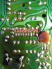
I was gonna take it in the shop for repair, but I was curious if anyone had the same experience with this model or maybe i might find it was just cold solder or a blown transistor. I see four large ones, two Sanken 2SC2921 and two Sanken 2SA1215, but can they be tested while in circuit? Do I have to unsolder them?
 

Attachments

  • IMG_20160713_042945.jpg
    IMG_20160713_042945.jpg
    250.2 KB · Views: 194
  • IMG_20160713_031355.jpg
    IMG_20160713_031355.jpg
    262.5 KB · Views: 146
  • IMG_20160713_043106.jpg
    IMG_20160713_043106.jpg
    269.2 KB · Views: 171
  • IMG_20160713_043210.jpg
    IMG_20160713_043210.jpg
    248.5 KB · Views: 144
  • IMG_20160713_043310.jpg
    IMG_20160713_043310.jpg
    292.7 KB · Views: 148
  • IMG_20160713_043402.jpg
    IMG_20160713_043402.jpg
    291 KB · Views: 141
  • IMG_20160713_044913.jpg
    IMG_20160713_044913.jpg
    267.1 KB · Views: 142
  • IMG_20160713_045433.jpg
    IMG_20160713_045433.jpg
    179.3 KB · Views: 176
  • IMG_20160713_044726.jpg
    IMG_20160713_044726.jpg
    92.5 KB · Views: 136

dorke

Jun 20, 2015
2,342
Joined
Jun 20, 2015
Messages
2,342
Hi Rick,
You have the protection LED on?
You should start with measuring the DC voltages on IC701 (TA7317-protection IC).
It is a 9pin SIP package.

DCV relative to GND (pin-4 of the IC or the chassis or the black(-) terminal of the speakers whichever is easiest)
The schematics show the normal non-protection state voltages.
What do you get?

PROTON protect.jpg

IMG_20160713_043310.jpg
 
Last edited:

73's de Edd

Aug 21, 2015
3,628
Joined
Aug 21, 2015
Messages
3,628
Sir Rick 79 . . . . .

Looking at YELLOW boxed area of the board photo below. does it look like R676 . . . .a 390 ohm 2 Watt film unit might be the principal cause of the heat generation in the "Hotter'n Hell " PCB's scorched area, and is being sooooo bad that it has carbonized the pcb?

OR have the associated solder connections crystallized ?

C647 is critical in this circuitry . . as are C645 and C644 . . ..if they have had a capacitance decline.

Also inspect any power devices 2SC2921 / 2SA1215 plus others and power resistors, that might handle heavy current in that audio output section, and inspect ALL solder joints vewy-vewy-VEWY closely for any "floaters"..

Thassssit . . . . .


SPECIFIC REFERENCING:


dHjCjqk.jpg


73's de Edd
 
Last edited by a moderator:

Rick79

Nov 26, 2014
283
Joined
Nov 26, 2014
Messages
283
Hi Rick,
You have the protection LED on?
You should start with measuring the DC voltages on IC701 (TA7317-protection IC).
It is a 9pin SIP package.

DCV relative to GND (pin-4 of the IC or the chassis or the black(-) terminal of the speakers whichever is easiest)
The schematics show the normal non-protection state voltages.
What do you get?

View attachment 27872

View attachment 27873

Hi, sorry for the delay, Yes the red protection light is on constantly. I'm not sure what direction the pins are numbered, but from 1-9 as I marked in the photo, I get the following DC voltage readings...

1) 3.13 V
2) 0.58 V
3) 0.00 V
4) I had to switch the meter to 200V & i got a reading of 44.1 V
5) - 0.74 V
6) 0.00 V
7) 0.63 V
8) 0.03 V
9) - 0.73 V
 

Attachments

  • IMG_20160727_172335.jpg
    IMG_20160727_172335.jpg
    347.6 KB · Views: 132

dorke

Jun 20, 2015
2,342
Joined
Jun 20, 2015
Messages
2,342
Rick,
you have counted the pins from the wrong side,it should be like that:

1) - 0.73 V
2) 0.03 V
3) 0.63 V
4) 0.00 V
5) - 0.74 V
6) I had to switch the meter to 200V & i got a reading of 44.1 V
7) 0.00 V
8) 0.58 V
9) 3.13 V

There are some problems here:
pin 8 (0.58V) is too low.

pin 3 (0.63v)is too high ==> that probably means there is DC voltage at the output of the Left channel.

Please check voltages on both sides of the resistors R654 and R655 (relative to chassis GND-4 readings).
BTW,
Is your amp in non-bridged mode? if it isn't put it in that state i.e bridged=off.

PROTON protect-1.JPG
 

Rick79

Nov 26, 2014
283
Joined
Nov 26, 2014
Messages
283
Rick,
you have counted the pins from the wrong side,it should be like that:

1) - 0.73 V
2) 0.03 V
3) 0.63 V
4) 0.00 V
5) - 0.74 V
6) I had to switch the meter to 200V & i got a reading of 44.1 V
7) 0.00 V
8) 0.58 V
9) 3.13 V

There are some problems here:
pin 8 (0.58V) is too low.

pin 3 (0.63v)is too high ==> that probably means there is DC voltage at the output of the Left channel.

Please check voltages on both sides of the resistors R654 and R655 (relative to chassis GND-4 readings).
BTW,
Is your amp in non-bridged mode? if it isn't put it in that state i.e bridged=off.

View attachment 28113

Yeah it's not in bridge mode, there's a plastic protective cover to prevent it from switching over to bridge mode so it's fine.

R665 reads 0.03 V & 0.00 V
R664 reads 0.63 V & 11.77 V
 

73's de Edd

Aug 21, 2015
3,628
Joined
Aug 21, 2015
Messages
3,628
.


Sir Rick79. . . . . . .

With your final two voltage readings given, one voltage reflects there being an excessive and imbalanced voltage present at the left side of R564. . . . . . with that excessive 11.77vdc voltage reading .
It is sampling from the common junction of the R647 / R645 emitter resistor junctions .
All is associated with the left channel of the power amp.
That voltage should normally be balanced out and be almost ZERO volts.
You have power output transistors Q615 and Q617 paired up.
Also driver transistor pairs Q611 and Q613.
Q609 quiescent biasing transistor interconnects between Q611 and Q613 driver transistors bases.
Q605 Q607 pre drivers and Q601 Q603 preamps also fill in the equation, with them ALL being in an interconnected DC loop.
WITH the qualifier being of all of them being in that interconnected / interrelated condition.

Now should you go back and measure across R647 emitter resistor versus its companion R465, it should have the greater voltage . Suggesting that channels top circuitry to the side and to the left should be most suspect.
If my nut to crack I would initially have the unit powered down and look over to that VR603 bias pot and measure its total resistance from one end to the other.
Note that it is hooked up "rheostat" mode so that it could swing from ~ 10 ohms tru ~100 0hms.
What I would be hoping to find was that its rotor connection had opened due to either connectivity or oxidation, such that it is open to 100 ohms.
If such is not the case, measure the resistance that it is presently set at and deoxidize, MULTI rotate it and leave some cleaner lube on its contacts and then reset to its found setting.
In the end, do the same procedure at the OTHER channels R604 equivalent control.

The GOOD thing now, is that you have the OTHER properly working channel to compare voltages against between identical CBE's of each channel to the other.

In the end, you could even do a "monkey see- monkey do" of swapping a transistor /diode from the bad channel over to the good working channel to find that part change that JUST shifts the working channel into a bad working state.

BTW . . . .do you want the very final last missing piece of the puzzle of that other amp that you were working with ?
If so, post back onto it.


73's de Edd


.
 

dorke

Jun 20, 2015
2,342
Joined
Jun 20, 2015
Messages
2,342
As expected there is DC voltage on the output of the left channel AMP.
Please put the volume at minimum and check the voltages on Q603 and Q609 relative to chassis GND.
 

Rick79

Nov 26, 2014
283
Joined
Nov 26, 2014
Messages
283
As expected there is DC voltage on the output of the left channel AMP.
Please put the volume at minimum and check the voltages on Q603 and Q609 relative to chassis GND.

Q603 reads on its 3 pins...
0.72 V
1.33 V
44.9 V

Q609 reads on its 3 pins...
11.82 V
14.10 V
12.61 V
 

dorke

Jun 20, 2015
2,342
Joined
Jun 20, 2015
Messages
2,342
Q603 reads on its 3 pins...
0.72 V ==> E
1.33 V ==> B
44.9 V ==> C

If these are indeed the "pin notations",
then Q603 and the voltages on it are fine.

Q609 voltages are all wrong !
11.82 V ==>E
14.10 V ==>C
12.61 V ==> B

Please verify the "pin" names as I noted them.
Q609 looks to be saturated,which it shouldn't be.

Please measure the DC voltages on both sides of R629 and R631,
and the voltages on Final TRs Q615,Q617 (with pin notations please).
 
Last edited:

73's de Edd

Aug 21, 2015
3,628
Joined
Aug 21, 2015
Messages
3,628
Q605 reads on its 3 pins...
V ==> E
V ==> B
V ==> C

Q607 reads on its 3 pins...
V ==> E
V ==> B
V ==> C
 

Rick79

Nov 26, 2014
283
Joined
Nov 26, 2014
Messages
283
Q605 reads on its 3 pins...
V ==> E
V ==> B
V ==> C

Q607 reads on its 3 pins...
V ==> E
V ==> B
V ==> C

Q605 Reads on its 3 pins...
45.5 V ==>E
13.9 V ==>B
45.0 V ==>C

Q607 Reads on its 3 pins...
13.7 V ==>E
45.6 V ==>B
14.4 V ==>C
 

Rick79

Nov 26, 2014
283
Joined
Nov 26, 2014
Messages
283
Q603 reads on its 3 pins...
0.72 V ==> E
1.33 V ==> B
44.9 V ==> C

If these are indeed the "pin notations",
then Q603 and the voltages on it are fine.

Q609 voltages are all wrong !
11.82 V ==>E
14.10 V ==>C
12.61 V ==> B

Please verify the "pin" names as I noted them.
Q609 looks to be saturated,which it shouldn't be.

Please measure the DC voltages on both sides of R629 and R631,
and the voltages on Final TRs Q615,Q617 (with pin notations please).


R629 Reads -21.1 V & 11.1 V
Im having a hard time finding R631 because some of the writings are under the components.

Q609
11.0 V ==>E
13.1 V ==>C
11.6 V ==>B

Q615
12.6 V ==>B
43.3 V ==>C
12.0 V ==>E

Q617
11.4 V==>B
- 43.1 V==>C
12.3 V ==>E

Can you check the photo I uploaded to see if I have the pinouts correct?
 

Attachments

  • IMG_20160730_034831.jpg
    IMG_20160730_034831.jpg
    316.9 KB · Views: 261

dorke

Jun 20, 2015
2,342
Joined
Jun 20, 2015
Messages
2,342
You have the pins correct.

I see you have re-measured Q609,the results are different(#9 vs #14).
Please repeat the measurement another time so we know what we have.

Q609 voltages are all wrong !
11.82 V ==>E
14.10 V ==>C
12.61 V ==> B

Q609
11.0 V ==>E
13.1 V ==>C
11.6 V ==>B

The reading on R629 ( -21.1 V & 11.1 V) are wrong !

Please check the DC voltage on R641 and R642(this one is on the other channel ).
What do we get?
 
Last edited:

Rick79

Nov 26, 2014
283
Joined
Nov 26, 2014
Messages
283
You have the pins correct.

I see you have re-measured Q609,the results are different(#9 vs #14).
Please repeat the measurement another time so we know what we have.

Q609 voltages are all wrong !
11.82 V ==>E
14.10 V ==>C
12.61 V ==> B

Q609
11.0 V ==>E
13.1 V ==>C
11.6 V ==>B

The reading on R629 ( -21.1 V & 11.1 V) are wrong !

Please check the DC voltage on R641 and R642(this one is on the other channel ).
What do we get?

DC Voltage on R641 is -21.1 V & -47.5 V
DC Voltage on R642 is -47.5 V & -26.8 V

I measured Q609 again. It reads...
11.1 V ==>E
13.6 V ==>C
12.1 V ==>B
 

dorke

Jun 20, 2015
2,342
Joined
Jun 20, 2015
Messages
2,342
I think something bad may have happened to R629(1.5K) and/or R641(1.2K).

Please disconnect the receiver from power.
Measure the DC voltages on R629 and R641 and make sure it is zero!
Only if there is indeed no voltage on the resistors check them in ohm(non-diode mode!).
You can compare the values with R630 and R642 of the good channel.
What do we get?
 
Last edited:

Rick79

Nov 26, 2014
283
Joined
Nov 26, 2014
Messages
283
How
I think something bad may have happened to R629(1.5K) and/or R641(1.2K).

Please disconnect the receiver from power.
Measure the DC voltages on R629 and R641 and make sure it is zero!
Only if there is indeed no voltage on the resistors check them in ohm(non-diode mode!).
You can compare the values with R^30 and R642 of the good channel.
What do we get?

With my Meter set on 2K ohms I get the following readings...
R629 1.491
R641 1.221
R630 1.504
R642 1.215
 

dorke

Jun 20, 2015
2,342
Joined
Jun 20, 2015
Messages
2,342
The resistors are fine,I miss calculated.

Please check DC voltages on both sides of D603 and R611,R633 relative to GND.

Please check the voltages on Q601,It's orientation is so:
q601.jpg
 
Last edited:

Rick79

Nov 26, 2014
283
Joined
Nov 26, 2014
Messages
283
The resistors are fine,I miss calculated.

Please check DC voltages on both sides of D603 and R611,R633 relative to GND.

Please check the voltages on Q601,It's orientation is so:
View attachment 28165


D603 reads 46.8 V & 47.4 V
R611 reads 47.7 V & 47.4 V
R633 reads 45.5 V & 47.1 V

Q601 reads
44.8 V ==>C
15.9 V ==>B
45.5 V ==>E
 
Top