Hi: I will continue along, report my steps, if only for my own sake, and if I run into a specific issue, i will ask. Let's hope it works.
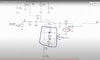
By the way, I tried to come up with a way to make easy for people to follow. I thought that if the narrative is read, and one looks at the schematic, it would take no time for an experienced person to note if I am off track. But perhaps this method works for me, but not for others. I apologize, I honestly thought it would be the simple way. Anyway, maybe I can report any questions if I come across them instead.