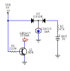
I've built a binary clock circuit that runs off of 5VDC from a USB connection (computer/wall adapter). The LEDs are all common cathode to 0V. I've wired it so the 5V from the USB switches an NPN transistor on to allow the LEDs to sink to 0V. That 5V then goes through a diode to the clock part of the circuit.
Then I've got a battery (preferably 9V for smaller physical size) going through another diode (to prevent any possible attempt of charging the alkaline) and again to the clock part of the circuit. The idea being that when plugged in, the LEDs will be lit (200mA or so) but when unplugged, the LEDs will be cut off, with the rest of the circuit continuing to keep the correct time.
My problem is that I would like to have it so when plugged in, there will not be any current drawn from the battery (or maybe a few uA). I've tried a 5V regulator, but that needs power to function even with little or no load. I've tried ~47kR of resistance between the battery and circuit, though that draws a little current still when the 5V is plugged in.
So, in short, is there a way to cut-off that leakage current from the battery (to preserve its life) when this 5V is present? Maybe with the use of a PNP transistor? I don't have a relay or I'd use that. I have this feeling that there's some simple way of doing this but I can't get it right. The circuit can operate 3-15V. I can make up a schematic if my explanation isn't clear enough.
Thanks