Maker Pro
Maker Pro

74HC138N: IC Beginnings Chapter Two

Simon101

Oct 8, 2014
38
Joined
Oct 8, 2014
Messages
38
Thanks to the great help on my first post, I've been working through a few more IC's and have now dived in to something a bit more complicated: the 74HC138N inverting demultiplexer http://www.nxp.com/documents/data_sheet/74HC_HCT138.pdf

Behavior is working perfectly as expected: numbering LED's from 0 to 7, input binary 0 turns off LED 0, binary 7 turns off LED 7 etc (and all other LED's remain on, because this is the "inverting" version of the chip)

Two questions:
1)
How do the three "enable" pins work? I can't make sense of the datasheet and can't find much info online. People mention the word "strobe" and linking up multiple chips... but pieces not really fitting together. According to my eyes, (my multimeter is all the way down in my car!) unless both E1 and E2 are low, and E3 is high, then ALL outputs = High.

2) Short of using transistors, could I have wired up my input pins any bit better? :) I've got three LED's linked to my Input = High: although previous post taught me about pull-up resistors (and i'm using them on enable lines) I couldn't think of how to apply the same theory if I wanted to also drive LED's in parallel with my input lines (short of using Transistors, of which I have none while waiting for Ebay shipment :) I don't have an actual "switch" per say, just hook-up cables I'm switching between +5V and GND... so input = floating in the second or so in between which I know is bad but perhaps not a huge deal for my basic "learning" application here...

Thanks for any insights :)


IMAG0044.jpg
 

Colin Mitchell

Aug 31, 2014
1,416
Joined
Aug 31, 2014
Messages
1,416
Imagine you have some of these 74138's on a bus we will call the "enable" and the bus contains 3 lines. How many 74138 can you separately activate with 3 lines?
Once you have "enabled" this particular 74138, you have another 3-line bus called "select" bus and this allows you to select 7 different chips.
 

KrisBlueNZ

Sadly passed away in 2015
Nov 28, 2011
8,393
Joined
Nov 28, 2011
Messages
8,393
Thanks to the great help on my first post, I've been working through a few more IC's and have now dived in to something a bit more complicated: the 74HC138N inverting demultiplexer http://www.nxp.com/documents/data_sheet/74HC_HCT138.pdf. Behavior is working perfectly as expected: numbering LED's from 0 to 7, input binary 0 turns off LED 0, binary 7 turns off LED 7 etc (and all other LED's remain on, because this is the "inverting" version of the chip)
That's great!
1) How do the three "enable" pins work? I can't make sense of the datasheet and can't find much info online. People mention the word "strobe" and linking up multiple chips... but pieces not really fitting together. According to my eyes, (my multimeter is all the way down in my car!) unless both E1 and E2 are low, and E3 is high, then ALL outputs = High.
That's exactly right. The reason this IC was designed with so many enable pins is to make it easier to use several of them together, to expand the number of inputs and outputs.

A single 138 expands three binary inputs into eight one-at-a-time outputs, right? But say you want to expand four binary inputs into 16 one-at-a-time outputs. Well, there's actually an IC that does that, but forget that for a minute. To decode four binary inputs using two 138s, you would have to use the new fourth bit to control which one of the 138s is enabled. One of the 138s needs to be enabled when the new fourth bit is low, and the other 138 needs to be enabled when the new fourth bit is high. With an active-low enable and an active-high enable on each 138, you can do this with no extra logic.
2) Short of using transistors, could I have wired up my input pins any bit better? :)
Yes! First, you don't need series resistors between the switches and the IC inputs. CMOS inputs have a very high input impedance but that doesn't mean that you need to drive them through very high-value resistors.
I've got three LED's linked to my Input = High: although previous post taught me about pull-up resistors (and i'm using them on enable lines) I couldn't think of how to apply the same theory if I wanted to also drive LED's in parallel with my input lines ...
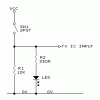
You can just drive both the LED and the input from the same switch, like this:
270764.001.GIF
When the switch is open, R1 pulls the IC input voltage down to 0V. There is no voltage across the R2+LED combination, so it doesn't light. When the switch is closed, it forces the VCC voltage onto the IC input signal, overriding the pull-down behaviour of R1. That voltage also appears across R2+LED and the LED lights up.

I've called the bottom supply rail "0V" and not used a ground symbol. That's because it doesn't really relate to "ground" - ground is the soil, and this rail isn't necessarily connected to the soil. It is the rail relative to which all voltages are measured, so I prefer to call it 0V ("zero volts"). Many people call it GND or use a ground symbol out of convention, but I think it's more useful to think of it as the "zero volt" reference rail of the circuit.
 

Simon101

Oct 8, 2014
38
Joined
Oct 8, 2014
Messages
38
Thanks guys! This gives me more homework :) I have another 138 so will try to make a 4bit input -> 16 (hmm also waiting on LED's from Ebay... I hope they show up soon!)

I find your post intriguingly cryptic Colin and it will haunt me in my dreams tonight I think. I'm sure will make sense soon :)

That diagram makes sense KrisBlue thanks for that! (a fellow Wellingtonian here, though in Melbourne ~8 years)
 

KrisBlueNZ

Sadly passed away in 2015
Nov 28, 2011
8,393
Joined
Nov 28, 2011
Messages
8,393
Thanks guys! This gives me more homework :) I have another 138 so will try to make a 4bit input -> 16 (hmm also waiting on LED's from Ebay... I hope they show up soon!)
OK :)
I find your post intriguingly cryptic Colin and it will haunt me in my dreams tonight I think. I'm sure will make sense soon :)
Don't obsess about it. "Intriguingly cryptic" and "poor communication skills" are two sides of the same coin!
That diagram makes sense KrisBlue thanks for that! (a fellow Wellingtonian here, though in Melbourne ~8 years)
Cool! My sister lives in Melbourne.
 
Last edited:

Simon101

Oct 8, 2014
38
Joined
Oct 8, 2014
Messages
38
actually i guess that's pretty easy isn't it, see what you're saying Kris. The fourth bit just needs to pull E1 or E2 on IC1 from low to high (to turn it off), and pull E3 on IC2 from low to high (to turn it on)

Then taken to it's logical conclusion (pun fully intended and I expect praise for it) I guess that feeds in to what you were saying Chris? If we had 6bit input, first 3 bits are kinda "output-n on IC" and the next 3 bits select IC-n, so we can address 1 of 64 outputs?

I shall go away and try to draw that up, as I can't quite picture how 3bits relate to E1, E2, and E3 pins...
 

Simon101

Oct 8, 2014
38
Joined
Oct 8, 2014
Messages
38
I guess one (or the simplest?) solution is just to use a ninth 738 with 8 outputs going to eight E1 or E2 pings on the 8 other IC's: the ninth 738 can just pull that low to enable corresponding IC

Or is there another way to go from 3bit input to exclusively select the IC using it's E1,E2 and E3 pins without using a ninth IC? *ponder*

[EDIT] Figured I'd better add an edit rather than keep on adding new posts!

After a bit of cider and some pondering I believe I can take three inputs, split them to three inverters, which gives me six inputs: then I just wire them in 8 unique ways to my 8 IC's

Difference between buying an inverter IC or another 738 IC...
 
Last edited:

KrisBlueNZ

Sadly passed away in 2015
Nov 28, 2011
8,393
Joined
Nov 28, 2011
Messages
8,393
Yes. If you want to decode six bits to a one-of-64 output, you need eight 138s, and three inverters to generate complemented versions of the top three bits. Each 138 will only activate on the appropriate combination of its three enable inputs, so you just connect the enable inputs of each 138 to the appropriate true or inverted signals.

Or as you say, you can decode the top three bits using a ninth 138, to produce eight active-low enables, one for each of the final 138s. This will cause a slightly longer propagation delay though.

And you could go to seven input bits, if you use the new highest-order bit to enable one or other set of final 138s, through their active high and active low enable inputs (the ones that aren't driven by the ninth 138), or you could use ten 138s.

All of this assumes that you want to expand a multi-bit binary value into a huge number of individual enable signals. I'm not sure why you would want to do that!

And congratulations on your "logical conclusion" pun. You are the punmaster ;-)
 
Top