- Joined
- Nov 28, 2011
- Messages
- 8,393
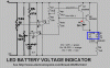
OK, here's my suggested circuit. The changes are only in the LED circuit.

Some features of this diagram are needed for LTSpice, the circuit simulation software, and aren't meant as changes from your original circuit.
R1~4 represent the two trimpots. They're shown as resistors in this diagram for simplicity. The actual value of the trimpots is not critical as long as they aren't so low that they waste significant current. Personally I would use 20k or 50k trimpots.
U1 and U2 are shown as separate LT1001 op-amps but that's just because LTSpice doesn't have the LM358 and it doesn't support dual op-amps properly. Use your LM358 as before.
The 2.5V reference voltage is shown as a voltage generator in the diagram, but should still be an LM336Z with a 27k resistor to VCC.
The LEDs are shown as a simple diode and an LED marked QTLP690C. That's because LTSpice doesn't have many LEDs. They should be a bi-colour (red/green) LED in a three-pin package with common cathode.
R5~10 and Q1,2 are genuine components. They're all new except R5, which replaces the two 1k5 resistors in the original design. This means that the current consumption of the LEDs is always about 10~15 mA, unlike the original design where the current consumption would be twice that much when both LEDs were ON simultaneously.
In this design, when both LEDs are ON, they share the current; the value of R6 determines how much current each LED gets, and therefore determines the shade of orange that you will get. You could replace R6 with a 500 ohm trimpot so you can fine-tune the orange colour to your preference.
How does it work? It relies on the fact that red and green LEDs have different forward voltages. When you feed 10 mA through a green LED, it will drop about 2.8V (typically), whereas 10 mA through a red LED will cause a voltage drop of about 1.8~2.0V.
When the supply voltage is greater than the highest threshold (I've used 22V here), the outputs of both op-amps are high, i.e. close to the positive rail. There will be little voltage across R7 and R9, and Q1 and Q2 will not conduct. You can ignore all of the LED circuitry apart from D1B (the green LED element) and R5.
A current of about 10~15 mA (depending on the battery voltage) will flow through D1B and R5, producing a green indication. There will be about 2.8V across D1B.
When the supply voltage drops below the higher threshold, U1's output will go low and this will turn Q1 ON. There is now a current path through Q1, R6 and D1A. Since D1A has a forward voltage of about 1.8V, there will be about 1V remaining across R6, and the value of R6 will determine how much current will flow through D1A. If you reduce R6, more current will flow through D1A and less current will remain to flow through D1B. This makes the orange indication closer to red. If you increase R6, the orange colour will become greener.
When the supply voltage drops below the lower threshold, U2's output will go low and Q2 will turn ON. This effectively connects D1A in parallel with D1B. Because D1A has a forward voltage of only 1.8V, there will not be enough voltage across D1B for D1B to draw any current, and the LED will indicate only red.
In all of these cases, as the battery voltage drops past each threshold, the current drawn by the circuit actually increases slightly. Each increase in load current will cause the battery voltage to fall slightly, and this change reinforces the change that caused it. This avoids all the situations where instability and oscillation can occur.
Those situations will only occur when a change (e.g. a drop in battery voltage) causes a change (e.g. a reduction in load current) that then reverses the original change (reduced load current will cause the battery voltage to rise). The system can get into an unstable state, with the battery voltage oscillating above and below the threshold voltage, because a change causes an effect that negates, or reverses, the change. With this design, all the effects reinforce the change; nothing negates the change. Therefore there's no need to add explicit hysteresis around either of the op-amps.
The other advantage that this design has over the original design is that its load current is fairly constant, as I said earlier. The original design draws 10~15 mA when indicating either red or green, but twice that when indicating orange. This design has a single current-setting resistor, and in the orange state, that current is split between the two elements of the LED.
")