Maker Pro
Maker Pro

555 on/off circuit for 5v motor (w/ schematic)

p1ne

Jun 3, 2015
27
Joined
Jun 3, 2015
Messages
27
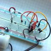
This PWM experiment has 6v coming out of NPN emitter (when "on"), which powers a 3 -6v mini water pump. Circuit works, but I want less "on time", and more consistent cycle, as compared to LED output, which is pretty consistent. I've changed values of capacitors/resistors, and the cycle varies, but the motor still stays on longer than I want. Increasing the resistor out of pin 3 helps some but also slows down the motor, which I don't want. The average on/off now is about 4 seconds, whereas I'd like "off" to be at least 4 seconds and "on" to be 1 -2 seconds. Thanks for guidance. pwm-on-off-motor.jpg
 

Alec_t

Jul 7, 2015
3,590
Joined
Jul 7, 2015
Messages
3,590
Try this modification. Separate pots are provided for the on and off time adjustments. D3 is a back-emf spike-suppressor.
MotorSwitcher.PNG

C1 needs to have low leakage if you want fairly consistent time periods. A 555 is not ideal for accurate long periods, especially where electrolytic capacitors are involved.
 
Last edited:

BobK

Jan 5, 2010
7,682
Joined
Jan 5, 2010
Messages
7,682
You can also improve the circuit by placing the transistor between the motor - terminal and ground. I.e.

motor + to V+
motor - to collector
emitter to ground

This will reduce the voltage drop across the transistor to about 0.2V and make the transistor run cooler.

Bob
 

p1ne

Jun 3, 2015
27
Joined
Jun 3, 2015
Messages
27
Thanks Alec that timing is perfect with an LED, and I'm getting 4.8v from the emitter junction, but it is not powering the 3v motor (even LED is dim). I've checked all leads and tested the motor, nothing. I have a feeling it's not getting enough current as I'm reading 2.7 mAh from emitter junction. The mini pump doesn't have operating current specs but I'm guessing it needs around 100 mAh.

I don't have the diodes you specified, so I used both germanium and Zener 1N4733, but with same 2.7 mAh on output. I've powered this with 2 #18650 3.7v 3000 mAh batteries in series = 7.4v or (6) 1.5volts, same results. Thanks in advance for guidance.

Also BobK, thanks just tried your advice, getting more voltage at emitter and tons of current at collector (4.8 amps, those #18650 are actually +5000 mAh), but the motor is still not running in this circuit.
 
Last edited:

CDRIVE

Hauling 10' pipe on a Trek Shift3
May 8, 2012
4,960
Joined
May 8, 2012
Messages
4,960
Also BobK, thanks just tried your advice, getting more voltage at emitter and tons of current at collector (4.8 amps, those #18650 are actually +5000 mAh), but the motor is still not running in this circuit.
This makes no sense. If you wired the motor as Bob described you shouldn't read any voltage on the Emitter as it would be connected to GND. If that little 2N2222 passed 4.8Amps for anything other than a short pulse time it should have destroyed itself.

Chris
 

p1ne

Jun 3, 2015
27
Joined
Jun 3, 2015
Messages
27
Chris/Bob, I replaced NPN and re-wired. Wiring with Chris' mod I get constant .5 v on output with no LED blinking. Wired with Bob's original, I'm getting 5 volts on output, 2.5 mAh at emitter, 4 amps at collector (using #18650 batteries in series), and LED blinks on/off but motor's not running.

I forgot to mention that I don't have 20/100K pots, only 10K. So I wired 20K & 100K resistors at NPN base/pin 3 junction per Bob's schematic. Should this still be working, and if so why isn't enough current being dispensed to motor? Thanks.
 
Last edited:

Alec_t

Jul 7, 2015
3,590
Joined
Jul 7, 2015
Messages
3,590
So I wired 20K & 100K resistors at NPN base/pin 3 junction
The only resistor going to the NPN base should be a 470 Ohm if you're using the post #2 circuit. This resistor should be connected between the base and pin 3.
 

p1ne

Jun 3, 2015
27
Joined
Jun 3, 2015
Messages
27
The only resistor going to the NPN base should be a 470 Ohm if you're using the post #2 circuit. This resistor should be connected between the base and pin 3.
Yes that's what I have. And pin 3 output is also going to 20/100K resistors which are sharing a junction like your schematic.
 

CDRIVE

Hauling 10' pipe on a Trek Shift3
May 8, 2012
4,960
Joined
May 8, 2012
Messages
4,960
When weird results are posted regarding circuits that we're intimately familiar with it's time for some clear photos.

Chris
 

p1ne

Jun 3, 2015
27
Joined
Jun 3, 2015
Messages
27
thanks for looking.
 

Attachments

  • 555-circuit.jpg
    555-circuit.jpg
    347.6 KB · Views: 72

CDRIVE

Hauling 10' pipe on a Trek Shift3
May 8, 2012
4,960
Joined
May 8, 2012
Messages
4,960
Looking at your photo I can confirm that you didn't wire the transistor as Bob suggested. From what I can derive from the photo it's still wired as a Emitter Follower, which as Bob pointed out is not the best configuration for saturating a transistor. That said an Emitter Follower should still work but it will run the transistor hotter. I tried following the base resistor connection to the 555 but it's not clear. It looks like it's connected to the Reset pin not the Output pin. That said the Reset pin is tied to Vcc so if it's connected there the transistor would be on and the motor would run all the time.

Personally I think your transistor is no longer a transistor and would be best described as a burnt open lump of silicon and plastic.

Chris
 

Alec_t

Jul 7, 2015
3,590
Joined
Jul 7, 2015
Messages
3,590
The electrolytic cap seems to be connected directly across the power rails; not as per the schematic.
 

CDRIVE

Hauling 10' pipe on a Trek Shift3
May 8, 2012
4,960
Joined
May 8, 2012
Messages
4,960
The electrolytic cap seems to be connected directly across the power rails; not as per the schematic.
Ah, that too! As usual photos clear up mysteries. ;)

Chris
 

(*steve*)

¡sǝpodᴉʇuɐ ǝɥʇ ɹɐǝɥd
Moderator
Jan 21, 2010
25,510
Joined
Jan 21, 2010
Messages
25,510
Another thing is that currents are measured in mA, not mAh. The latter is like speed being measured in metres.
 

p1ne

Jun 3, 2015
27
Joined
Jun 3, 2015
Messages
27
The electrolytic cap seems to be connected directly across the power rails; not as per the schematic.
Where does the negative terminal go then? Thanks.

Re: Cdrive, the base resistor is connected to pin 3, not pin 4.
 

CDRIVE

Hauling 10' pipe on a Trek Shift3
May 8, 2012
4,960
Joined
May 8, 2012
Messages
4,960
I think it's time for some basic troubleshooting. Wire your motor as shown here and tell us if the motor runs when you close the switch. If you don't have a switch then just use a jumper to open and close the base circuit. This way we'll know if your transistor is still with us or gone to silicon heaven. BTW I think R1 should be closer to 150Ω to fully saturate the 2N2222 but it's dependent on what the motor draws. The 470Ω should work for this test though.

Chris

upload_2017-1-30_22-33-48.png
 
Last edited:

CDRIVE

Hauling 10' pipe on a Trek Shift3
May 8, 2012
4,960
Joined
May 8, 2012
Messages
4,960
Where does the negative terminal go then? Thanks.

.
It goes to GND as you have it but the + pin shouldn't be connected to the +5V rail.

Chris
 

p1ne

Jun 3, 2015
27
Joined
Jun 3, 2015
Messages
27
Thanks Alec, Chris, circuit/motor working great, 2 seconds on, 8 off, fairly consistent too. The capacitor's + pin is connected to + terminal of D2, like Alec's schematic. It's not connected to V+. (I can see why you said that...that wire is orange wire bridging V+ sections on breadboard.)

I'm pretty sure the problem had to do with D3 connection. I don't like jamming these diodes into breadboard because it ruins holes, so I had D3 rigged to jumper wires before taking the picture, but decided to jam it in holes for picture clarity. Anyhow, the jumper wire hack must have been the problem because the circuit works great now (with all diodes in breadboard).

Bob, with this working circuit, when I connected motor + to V+, motor - to collector, and emitter to ground (no diode), by NPN got fried (and motor didn't run).

Also thanks Steve for mA not mAh hours reminder. Current reading is not about battery current capacity.
 
Last edited:

CDRIVE

Hauling 10' pipe on a Trek Shift3
May 8, 2012
4,960
Joined
May 8, 2012
Messages
4,960
Bob, with this working circuit, when I connected motor + to V+, motor - to collector, and emitter to ground (no diode), by NPN got fried (and motor didn't run).

.
It should have been wired like this and omitting the Diode is an invitation to back EMF destruction of the transistor.

Chris

upload_2017-1-31_9-12-9.png
 

p1ne

Jun 3, 2015
27
Joined
Jun 3, 2015
Messages
27
That's great, thanks. Outputs 5.5v which is perfect for 3 - 6v motor. At first with your revision, I was frying yet another NPN until I decided to remove the connection between between collector and pin 8 (V+), thinking that putting 2 V+ connections to 1 collector wasn't a good idea. Then everything worked great.
 
Top