Mastermind
- Jul 29, 2011
- 29
- Joined
- Jul 29, 2011
- Messages
- 29
Hey guys,
I am soldering a 1N4148 Logic Diode to this relay
http://www.amazon.com/Parts-Express-1N4148-Logic-Diode/dp/B0002KRC7C
I am using this diode to dampen the reversed polarity high voltage pulse when removing the voltage from the relay.
I am basically just using the relay and this rocker switch as a high current allowing on/off switch.
http://www.amazon.com/gp/product/B001TQKKMC/ref=oh_o03_s00_i00_details
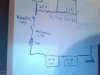
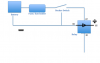
I am having trouble figuring out where to connect everything. Heres what I have so far.
Diode soldered onto terminals 85 and 86 (Which way do I solder the diode on? Also which side of the diode is anode and which side is cathode?)
Input: terminal 87
Output:terminal 30
Where do I put the rocker switch? On the input?
Thanks
I am soldering a 1N4148 Logic Diode to this relay
http://www.amazon.com/Parts-Express-1N4148-Logic-Diode/dp/B0002KRC7C
I am using this diode to dampen the reversed polarity high voltage pulse when removing the voltage from the relay.
I am basically just using the relay and this rocker switch as a high current allowing on/off switch.
http://www.amazon.com/gp/product/B001TQKKMC/ref=oh_o03_s00_i00_details
I am having trouble figuring out where to connect everything. Heres what I have so far.
Diode soldered onto terminals 85 and 86 (Which way do I solder the diode on? Also which side of the diode is anode and which side is cathode?)
Input: terminal 87
Output:terminal 30
Where do I put the rocker switch? On the input?
Thanks