Project Log
My 'Fanrunon' project is a turn-off delay timer module for use with an AC mains load such as a fan or a light. The rated maximum current is 2.5A RMS. It uses a triac for switching, and a Microchip PIC12F675 microcontroller.
At this time, I have not built up the hardware, and I have only partly tested the firmware using the Microchip MPLAB X emulator. The design and/or the code may change once I have built and tested the circuit and the code.
The module fits inside the cavity behind the wall switch, and receives its power from the fan current itself. Because of this design feature, and unlike many commercial turn-off delay timers, this design doesn’t require a Neutral wire in the switch cavity.
Fanrunon uses the mains frequency as its timing source, and supports 50 and 60 Hz mains frequencies. The run-on time can be selected by switching the wall switch ON and OFF a certain number of times. The wall switch must be a changeover type (SPDT aka SPCO) so the circuit can detect its position.
Since the Fanrunon module doesn’t connect across the mains (it doesn’t use a Neutral connection), it gets its operating power by slightly dropping the voltage available to the load.

Circuit description:
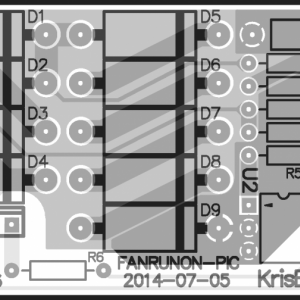
Turning ON the wall switch completes the electrical circuit from mains Phase, through the Fanrunon circuit (CN1 pins 1 and 2), through the wall switch, through the fan, and back to mains Neutral, and this powers up the Fanrunon circuit. D1~4 form a bridge rectifier that ensures that the voltage across the series diode string D5~9 always has the right polarity — positive at the top. The diode string conducts the load current and limits the voltage across it to around 5V (depending on load current). On every half-cycle of the mains waveform, current flows through D1~4 and produces this voltage drop across the diode string.
This 5V supply rail passes through fusible resistor R1 to D10, a 5.1V zener diode. This arrangement ensures that if excess current flows through the D5~9 string (due to a short-circuited fan or a wiring error), D5~9 may be damaged but R1 will very quickly go open-circuit, while D10 protects the microcontroller from losing its smoke. C1 smooths the DC rail so it remains active around zero-crossings of the mains voltage, when there is insufficient voltage available at the bridge rectifier input. This provides a 5V DC (approximately) supply to the microcontroller.
U1 is a Microchip PIC12F675-I/P microcontroller in an 8-pin DIP package. CN2 is the ICSP (in-circuit serial programming) connector which enables the firmware to be programmed into U1 using a Microchip PICkit 2 or PICkit 3 USB programming device.
U1 uses an internal factory-calibrated R-C oscillator operating at about 4 MHz. It also uses an internal power-up reset circuit and brown-out detector, so pin 4 (-MCLR) is not used, except as VPP during in-circuit programming.
Only three I/O pins are used on U1. Pin 2 drives piezo transducer X1 which provides audio feedback to the user. Pin 2 is referred to as "PZO" in the source code. X1 is a simple transducer, not a beeper. The PIC generates the beep frequencies internally.
Pin 3, "fan enable", is referred to as "FEN" in the source code. It drives U2, an MOC3063 or TLP3063 triac driver IC, which drives triac Q1, which is connected in parallel with the ON contact of the wall switch via CN1 pin 4 and can keep the load and the Fanrunon circuit energised even when the wall switch is OFF. When U1 drives pin 3 high, the LED in U2 illuminates and causes its output circuit to trigger Q1. U2's output circuit includes a zero crossing detector which ensures that Q1 is only turned ON and OFF when the voltage across it crosses zero. This minimises generated interference. R7 and C2 form a snubber network to reduce the effect of noise on the mains supply and voltage spikes due to the load inductance.
U1 pin 5 is driven from the OFF contact of the wall switch via CN1 pin 3. This signal is referred to as "SAC" ("switched AC") in the source code. While the wall switch is in the OFF position, this signal will have a rectangular wave at the AC mains frequency, with a duty cycle between 30% and 70%. When the wall switch is in the ON position, this signal is pulled low by R2. This signal is used by the firmware to (a) detect the AC mains frequency (50 and 60 Hz are supported), (b) provide an accurate timing source for measuring the hold-on period, and (c) determine the position of the wall switch.
Here is the source code, written in assembly language for the mid-range PIC microcontroller, in its current state. It assembles properly with MPLAB X version 2.00 but may contain bugs and has not been tested.
At this time, I have not built up the hardware, and I have only partly tested the firmware using the Microchip MPLAB X emulator. The design and/or the code may change once I have built and tested the circuit and the code.
The module fits inside the cavity behind the wall switch, and receives its power from the fan current itself. Because of this design feature, and unlike many commercial turn-off delay timers, this design doesn’t require a Neutral wire in the switch cavity.
Fanrunon uses the mains frequency as its timing source, and supports 50 and 60 Hz mains frequencies. The run-on time can be selected by switching the wall switch ON and OFF a certain number of times. The wall switch must be a changeover type (SPDT aka SPCO) so the circuit can detect its position.
Since the Fanrunon module doesn’t connect across the mains (it doesn’t use a Neutral connection), it gets its operating power by slightly dropping the voltage available to the load.
Circuit description:
Turning ON the wall switch completes the electrical circuit from mains Phase, through the Fanrunon circuit (CN1 pins 1 and 2), through the wall switch, through the fan, and back to mains Neutral, and this powers up the Fanrunon circuit. D1~4 form a bridge rectifier that ensures that the voltage across the series diode string D5~9 always has the right polarity — positive at the top. The diode string conducts the load current and limits the voltage across it to around 5V (depending on load current). On every half-cycle of the mains waveform, current flows through D1~4 and produces this voltage drop across the diode string.
This 5V supply rail passes through fusible resistor R1 to D10, a 5.1V zener diode. This arrangement ensures that if excess current flows through the D5~9 string (due to a short-circuited fan or a wiring error), D5~9 may be damaged but R1 will very quickly go open-circuit, while D10 protects the microcontroller from losing its smoke. C1 smooths the DC rail so it remains active around zero-crossings of the mains voltage, when there is insufficient voltage available at the bridge rectifier input. This provides a 5V DC (approximately) supply to the microcontroller.
U1 is a Microchip PIC12F675-I/P microcontroller in an 8-pin DIP package. CN2 is the ICSP (in-circuit serial programming) connector which enables the firmware to be programmed into U1 using a Microchip PICkit 2 or PICkit 3 USB programming device.
U1 uses an internal factory-calibrated R-C oscillator operating at about 4 MHz. It also uses an internal power-up reset circuit and brown-out detector, so pin 4 (-MCLR) is not used, except as VPP during in-circuit programming.
Only three I/O pins are used on U1. Pin 2 drives piezo transducer X1 which provides audio feedback to the user. Pin 2 is referred to as "PZO" in the source code. X1 is a simple transducer, not a beeper. The PIC generates the beep frequencies internally.
Pin 3, "fan enable", is referred to as "FEN" in the source code. It drives U2, an MOC3063 or TLP3063 triac driver IC, which drives triac Q1, which is connected in parallel with the ON contact of the wall switch via CN1 pin 4 and can keep the load and the Fanrunon circuit energised even when the wall switch is OFF. When U1 drives pin 3 high, the LED in U2 illuminates and causes its output circuit to trigger Q1. U2's output circuit includes a zero crossing detector which ensures that Q1 is only turned ON and OFF when the voltage across it crosses zero. This minimises generated interference. R7 and C2 form a snubber network to reduce the effect of noise on the mains supply and voltage spikes due to the load inductance.
U1 pin 5 is driven from the OFF contact of the wall switch via CN1 pin 3. This signal is referred to as "SAC" ("switched AC") in the source code. While the wall switch is in the OFF position, this signal will have a rectangular wave at the AC mains frequency, with a duty cycle between 30% and 70%. When the wall switch is in the ON position, this signal is pulled low by R2. This signal is used by the firmware to (a) detect the AC mains frequency (50 and 60 Hz are supported), (b) provide an accurate timing source for measuring the hold-on period, and (c) determine the position of the wall switch.
Here is the source code, written in assembly language for the mid-range PIC microcontroller, in its current state. It assembles properly with MPLAB X version 2.00 but may contain bugs and has not been tested.
Code:
; fanrunon.asm
; Kris Heidenstrom
; [email protected]
list b=4,c=240,n=0,r=dec ; Numeric constants are decimal
; 2014-01-06.001 Started
; 2014-02-18.002 First complete version
; 2014-02-28.003 Fixed logic in SACMon; detects mains frequency in simulator
;
; Target: Microchip PIC12F675 using internal oscillator at 4 MHz nominal.
; This is a mid-range PIC device (8-bit data, 14-bit-wide instruction word).
;
; This firmware controls a PIC microcontroller in a "fanrunon" circuit.
; This is a circuit that can be retrofitted to an AC mains-powered fan that
; extracts steam from a bathroom, or some similar load, that was previously
; controlled by a wall switch, to provide a run-on time or delayed turn-off
; so the user can leave the room and the fan will turn off automatically.
;
; The fanrunon module is installed into the cavity behind the wall switch, and
; the wiring is changed. The fanrunon module doesn't need a Neutral wire; it
; gets its operating voltage by being connected in series with the fan.
;
; The fanrunon module requires that the wall switch is a changeover type.
; The first (normally open) contact completes the circuit initially, activating
; the fan and energising the circuit. The circuit immediately enables a triac
; that is connected in parallel with the switch, keeping the fan and fanrunon
; module powered.
;
; The second (normally open) contact on the switch is monitored by firmware
; via the "SAC" (switched AC) input; this allows the user to turn the wall
; switch ON and OFF a number of times to select between several run-on times,
; as well as cancel the run-on feature if desired. The SAC input receives an
; AC signal at AC mains frequency while the wall switch is in the OFF position.
;
; The fanrunon module also has a piezoelectric transducer to provide audible
; feedback to the user.
;
; MCU pin allocation
;
; # Capabilities Used as Connected to
; 1 VDD VDD Circuit VCC
; 2 GPIO5/T1CKI/OSC1/CLKIN D.OUT Piezo transducer (returned to VCC)
; 3 GPIO4/-T1G/OSC2/CLKOUT D.OUT Active-high triac enable output
; 4 GPIO3/-MCLR/VPP VPP ICSP connector (33k pullup to VCC)
; 5 GPIO2/T0CKI/INT/COUT D.IN Mains frequency pulses while wall switch is OFF
; 6 GPIO1/CIN-/ICSPCLK ICSPCLK ICSP connector only
; 7 GPIO0/CIN+/ICSPDAT ICSPDAT ICSP connector only
; 8 VSS VSS Circuit 0V
;
;-------------------------------------------------------------------------------
; General operating information
;
; Digital I/O map: See GPIO register allocation, below
; Interrupt sources: None used
; Sleep mode: Not used
; Internal oscillator: Used; calibrated (4 MHz nominal)
; Watchdog: Not used
; Power-on reset: Internal (no external reset circuit on pin 4)
; -MCLR (pin 4) function: Disabled
; Brown-out detector: Used; threshold is fixed at 2.1V typical
; Power-up timer: Enabled
; EEPROM: Not used
; RAM: Used; 64 bytes total are available
; Flash ROM: Used; 1024 words total are available.
; Voltage reference: Not used; disabled
; Analogue comparator: Not used; disabled
; 10-bit ADC: Not used; disabled
; Timer 0: Used for timekeeping (tick on every wraparound)
; Timer 1: Not used; disabled
; ICSP: Used; pins are not shared with any other functions
;
; Register bank select: Bank 1 is used during initialisation only.
; From then on, bank 0 is always selected.
; PCLATH: Always kept at 0x00. Program memory is 1024 words
; in the PIC12C675. Calculated gotos will only work
; within the first 256 words.
;
;-------------------------------------------------------------------------------
; Configuration word:
;
; D C B A 9 8 7 6 5 4 3 2 1 0
; x x . . . . . . . . . . . . BG1-0: set at factory; preserved by Microchip programmer
; . . x x x . . . . . . . . . Unimplemented
; . . . . . 1 . . . . . . . . -CPD: data memory (EEPROM) protection (1 = no protection)
; . . . . . . 1 . . . . . . . -CP: program memory code protection (1 = no protection)
; . . . . . . . 1 . . . . . . BODEN: brown-out detector enable (1 = enable)
; . . . . . . . . 0 . . . . . MCLRE: MCLR pin function (0 disables MCLR function on pin)
; . . . . . . . . . 0 . . . . -PWRTE: Power-up Timer Enable (0 = enable)
; . . . . . . . . . . 0 . . . WDTE: Watchdog enable/disable (0 = disable)
; . . . . . . . . . . . 1 0 0 FOSC2-0: 1,0,0 = internal osc, GP4 and GP5 pins as I/O
;
;-------------------------------------------------------------------------------
; INITIAL REGISTER VALUES
;
; STATUS register (0x03) INITIALISED TO 0x00 THEN MODIFIED
; 7 6 5 4 3 2 1 0
; 0 . . . . . . . IRP: Unimplemented in this variant
; . 0 . . . . . . RP1: Unimplemented in this variant
; . . * . . . . . RP0: Selects register bank (0 = 0x00~0x7F; 1 = 0x80~0xFF)
; . . . x . . . . -TO: Clear at startup indicates a watchdog timeout occurred (read-only)
; . . . . x . . . -PD: Cleared by a SLEEP instruction to enter power-down (read-only)
; . . . . . x . . Z: Zero flag
; . . . . . . x . DC: Digit carry flag
; . . . . . . . x C: Carry flag
;-------------------------------------------------------------------------------
; FILE REGISTER USAGE
; GPIO register (0x05) (digital inputs and outputs) INITIALISED
; 7 6 5 4 3 2 1 0
; 0 0 . . . . . . Unimplemented
PZO EQU 5 ; . . 1 . . . . . GPIO5: PZO: output to piezo transducer - initially high
FEN EQU 4 ; . . . 1 . . . . GPIO4: FEN: fan enable output to triac (initially high to enable triac)
; . . . . x . . . GPIO3: -MCLR pin, used for ICSP only (VPP); input only
SAC EQU 2 ; . . . . . x . . GPIO2: SAC: input from AC mains pulses from wall switch OFF (else 0)
; . . . . . . 1 . GPIO1: ICSP signal only; set to output and driven high
; . . . . . . . 1 GPIO0: ICSP signal only; set to output and driven high
GPIO_initvalue EQU b'00110011'
; INTCON register (0x0B) (interrupt control and status) INITIALISED TO 0x00
; 7 6 5 4 3 2 1 0
; 0 . . . . . . . GIE: Global interrupt enable
; . 0 . . . . . . PEIE: Peripheral interrupts enable
; . . 0 . . . . . T0IE: Timer 0 overflow interrupt enable
; . . . 0 . . . . INTE: GP2 pin interrupt enable
; . . . . 0 . . . GPIE: GPIO port state change interrupt enable
; . . . . . 0 . . T0IF: Flag for timer 0 overflow (must be reset by firmware)
; . . . . . . 0 . INTF: Flag for GP2 pin interrupt
; . . . . . . . 0 GPIF: Flag for GPIO port state change interrupt
; PIR1 register (0x0C) (second peripheral interrupt request register) NOT INITIALISED
; 7 6 5 4 3 2 1 0
; 0 . . . . . . . EEIF: EEPROM interrupt flag (must be cleared by firmware)
; . 0 . . . . . . ADIF: ADC interrupt flag (must be cleared by firmware)
; . . 0 0 . . . . Unimplemented
; . . . . 0 . . . CMIF: Comparator interrupt flag (must be cleared by firmware)
; . . . . . 0 0 . Unimplemented
; . . . . . . . 0 TMR1IF: Timer 1 interrupt flag (must be cleared by firmware)
;
; None of those interrupt sources are enabled via PIE1 so PIR1 doesn't need to
; be initialised.
; T1CON register (0x10) (Timer 1 control) NOT INITIALISED (reset default is 0x00)
; 7 6 5 4 3 2 1 0
; 0 . . . . . . . Unimplemented
; . 0 . . . . . . TMR1GE: Gating enable (irrelevant if TMR1ON = 0)
; . . 0 0 . . . . T1CKPS1-0: Prescale select (ditto)
; . . . . 0 . . . T1OSCEN: Enables T1 low power oscillator
; . . . . . 0 . . -T1SYNC: Clear to enable synchronisation for external clock
; . . . . . . 0 . TMR1CS: Timer 1 clock source (0 = internal, Fosc/4)
; . . . . . . . 0 TMR1ON: Enable Timer 1 (0 = disable)
; CMCON register (0x19) (comparator control) INITIALISED
; 7 6 5 4 3 2 1 0
; 0 . . . . . . . Unimplemented
; . x . . . . . . COUT: Comparator output state (read-only)
; . . 0 . . . . . Unimplemented
; . . . 0 . . . . CINV: Invert comparator output flag (don't care)
; . . . . 0 . . . CIS: Determines input connection for modes 5,6 (don't care)
; . . . . . 1 1 1 CM2-0: Comparator mode. Mode 7: disable and power down.
CMCON_initvalue EQU b'00000111'
; ADCON0 register (0x1F) (ADC control) NOT INITIALISED (reset default is 0x00)
; 7 6 5 4 3 2 1 0
; 0 . . . . . . . AFFM: Format (right- or left-justified) (don't care)
; . 0 . . . . . . VCFG: ADC reference voltage source (0 = VCC) (don't care)
; . . 0 0 . . . . Unimplemented
; . . . . 0 0 . . CHS1-0: Input channel select (0-3) (don't care)
; . . . . . . 0 . GO/-DONE: Bit to trigger conversion (resets to 0 when done)
; . . . . . . . 0 ADON: Enable/disable ADC (0 = disable)
; OPTION_REG register (0x81) (miscellaneous options) INITIALISED
; 7 6 5 4 3 2 1 0
; 1 . . . . . . . -GPPU: GPIO pullup control (1 disables all pull-ups)
; . 0 . . . . . . INTEDG: Specifies interrupt edge for GP2/INT (not used; don't care)
; . . 0 . . . . . T0CS: T0 clock source (0 selects Fosc/4)
; . . . 0 . . . . T0SE: Specifies edge for GP2/T0CKI (not used; don't care)
; . . . . 0 . . . PSA: Prescaler assignment (0 = Timer0; 1 = watchdog)
; . . . . . 0 0 1 PS2-0: Selects prescaler division; 0,0,1 = divide by 4
#define OPTIONREG_initvalue b'10000001'
; TRISIO register (0x85) (tri-state enable for digital I/O) INITIALISED
; 7 6 5 4 3 2 1 0
; 0 0 . . . . . . Unimplemented
; . . 0 . . . . . TRISIO5: output mode (PZO)
; . . . 0 . . . . TRISIO4: output mode (FEN)
; . . . . 1 . . . TRISIO3: always an input anyway
; . . . . . 1 . . TRISIO2: input mode (SAC)
; . . . . . . 0 . TRISIO1: output mode
; . . . . . . . 0 TRISIO0: output mode
#define TRISIO_initvalue b'00001100'
; PIE1 register (0x8C) (second peripheral interrupt enable register) INITIALISED TO 0x00
; 7 6 5 4 3 2 1 0
; 0 . . . . . . . EEIE: EEPROM interrupt enable
; . 0 . . . . . . ADIE: ADC interrupt enable
; . . 0 0 . . . . Unimplemented
; . . . . 0 . . . CMIE: Comparator interrupt enable
; . . . . . 0 0 . Unimplemented
; . . . . . . . 0 T1IE: Timer 1 interrupt enable
; PCON register (0x8E) (power conditions) NOT INITIALISED
; 7 6 5 4 3 2 1 0
; 0 0 0 0 0 0 . . Unimplemented
; . . . . . . 1 . -POR: Cleared by hardware after a POR; must be set by firmware
; . . . . . . . 1 -BOD: Cleared by hardware after a BOD; must be set by firmware
; OSCCAL register (0x90) (on-board RC oscillator calibration register) INITIALISED
; 7 6 5 4 3 2 1 0
; x x x x x x . . OSCCAL5-0: Calibration value for internal RC oscillator
; . . . . . . 0 0 Unimplemented
;
; OSCCAL is set to the value in W after the fixed location 0x03FF has been
; called. The programmer and/or factory places a retlw instruction at that
; location, which returns the value that was determined to give the correct
; oscillator frequency.
; WPU register (0x95) (weak pullup enable) NOT INITIALISED
; 7 6 5 4 3 2 1 0
; 0 0 . . . . . . Unimplemented
; . . 0 . . . . . WPU5: no weak pullup
; . . . 0 . . . . WPU4: no weak pullup
; . . . . 0 . . . Unimplemented
; . . . . . 0 . . WPU2: no weak pullup
; . . . . . . 0 . WPU1: no weak pullup
; . . . . . . . 0 WPU0: no weak pullup
;
; This register doesn't affect anything because -GPPU in OPTION_REG is set.
; IOC register (0x96) (interrupt-on-change enable) INITIALISED TO 0x00
; 7 6 5 4 3 2 1 0
; 0 0 . . . . . . Unimplemented
; . . 0 . . . . . IOC5: no interrupt on change
; . . . 0 . . . . IOC4: no interrupt on change
; . . . . 0 . . . IOC3: no interrupt on change
; . . . . . 0 . . IOC2: no interrupt on change
; . . . . . . 0 . IOC1: no interrupt on change
; . . . . . . . 0 IOC0: no interrupt on change
; VRCON register (0x99) (voltage reference control) NOT INITIALISED (reset default is 0x00)
; 7 6 5 4 3 2 1 0
; 0 . . . . . . . VREN: Enable/disable voltage reference (0 = disable)
; . 0 . . . . . . Unimplemented
; . . 0 . . . . . VRR: Range selection (don't care)
; . . . 0 . . . . Unimplemented
; . . . . 0 0 0 0 VR3-0: Voltage reference selection (don't care)
; EECON1 register (0x9C) (EEPROM control) NOT INITIALISED (reset default is 0x00)
; 7 6 5 4 3 2 1 0
; 0 0 0 0 . . . . Unimplemented
; . . . . 0 . . . WRERR: Set by hardware to indicate an EEPROM write error
; . . . . . 0 . . WREN: Enables write cycles when 1
; . . . . . . 0 . WR: Initiates a write cycle when set
; . . . . . . . 0 RD: Initiates a read cycle when set
; ANSEL register (0x9F) (ADC clock and input pin type selection) INITIALISED TO 0x00
; 7 6 5 4 3 2 1 0
; 0 . . . . . . . Unimplemented
; . 0 0 0 . . . . ADCS2-0: ADC clock selection (0,0,0 = Fosc/2) (don't care)
; . . . . 0 0 0 0 ANS3-0: ADC input pin analogue selection (1 = analogue)
;
; Important! ANS3-0 are all 1 after a reset; this enables analogue input
; behaviour on those pins (and disables digital functions) by default.
; These bits MUST be cleared by firmware if the pins are to be used for
; digital functions.
;
;-------------------------------------------------------------------------------
; TIMEKEEPING
;
; The following frequencies assume that the internal oscillator frequency is
; exactly 4.000 MHz so the instruction cycle period is exactly 1 us.
;
; Timer 0 is an 8-bit free-running UP-counter. It is clocked from the 1 MHz
; (nominal) instruction clock prescaled by four, and wraps around every 256
; clocks, i.e. every 1.024 ms (nominally). Each wraparound sets the T0IF flag
; in INTCON, which is detected and cleared by WaitTick. The fan run-on period
; is timed using the AC mains-frequency signal on the SAC pin, for accuracy.
; The mains frequency is detected (50 and 60 Hz are supported) by measuring
; the interval between mains cycles on SAC using timer 0.
;
; Nominal (ideal) frequencies are:
;
; Fosc 4.0 MHz
; Fosc/4 1.0 MHz
; Instruction cycle period 1.0 us
; Timer 0 prescaler output period 4.0 us
; Timer 0 clock input period 4.0 us
; Timer 0 wraparound interval 1.024 ms
; Tick interval 1.024 ms
; TickCount increment interval 1.024 ms
; TickCount wrap-around interval 262.144 ms
;
;-------------------------------------------------------------------------------
; OPERATION AND USE
;
; This code controls a PIC16F675 microcontroller in a circuit that is connected
; to an AC mains wall switch for a load such as a light or fan. Its purpose is
; to delay the turn-off of the load by a selectable period of time.
;
; The circuit is specifically designed to work without a Neutral connection,
; and gets its operating power from the current flowing in the load. In other
; words, it is connected in series with the load.
;
; When the wall switch is first turned ON, the circuit powers up and this code
; starts running. It asserts its FEN (fan enable) output, which enables a triac
; that is connected across the wall switch. This keeps the load powered, and the
; circuit running. The user then turns the wall switch off, and may turn it ON
; and OFF again one or more times to select longer run-on times. When the wall
; switch has been OFF for a short time, the circuit enters run-on mode, where
; it keeps the fan running for a period of time. Then it drops its FEN output,
; the triac turns OFF, and the load and the circuit lose power.
;
; The wall switch must be a changeover type; when it is in the OFF position, AC
; voltage is switched to the OFF contact and is detected by firmware on the SAC
; input. Firmware uses this signal as the timing source for the turn-off delay.
;
; The fanrunon firmware can be controlled through the wall switch. It also
; announces its status through a piezo transducer which is driven from the PZO
; output from the MCU, and can produce beeps at two frequencies (low frequency,
; about 244 Hz, and high frequency, about 488 Hz). This is how to use it.
;
; 1. When the wall switch is initially switched ON, the load and the fanrunon
; circuit power up. Firmware asserts FEN so it will not lose power when the
; wall switch is turned OFF. Firmware monitors the wall switch state using
; the SAC input.
; 2. The user can switch the wall switch ON and OFF again, one or more times,
; as long as those timeouts are not exceeded.
; 3. As long as the wall switch does not remain OFF for a time determined by
; HoldT16, nor ON for a time determined by CroakT16, firmware keeps FEN
; active and continues to monitor the wall switch for more ON-OFF actions.
; 4. Each time the wall switch is changed from ON to OFF, firmware issues a
; confirmation beep at low pitch with a duration determined by BD_SwAck.
; 5. This allows the user to choose the run-on time as one of the predefined
; periods ROT1, ROT2, etc. One ON-to-OFF transition selects ROT1, two
; ON-to-OFF transitions select ROT2, etc. More than the maximum ROTn number
; is translated to ROT0, which is a ten second delay that can be used when
; testing.
; 6. When the wall switch has remained OFF for a time determined by HoldT16,
; firmware enters the run-on phase. It first issues a string of beeps at
; low pitch with a duration of BD_Annc, the number of beeps being equal to
; the number of ON-to-OFF transitions on the wall switch (or eight if more
; than the highest valid number of transitions occurred), then it begins
; counting down the time from the chosen ROTn value.
; 7. When the selected time expires, firmware issues a low-pitched beep of
; duration BD_Croak, deasserts its FEN output, and enters an endless loop.
; The load, and the circuit, will power down.
; 8. If at any time (including during the run-on period) the wall switch is
; turned ON and left ON for longer than the period set by CroakT16, firmware
; jumps to Croak - it issues a low-pitched beep with duration BD_Croak,
; deasserts FEN, and enters an endless loop. The load and the circuit will
; remain powered while the wall switch is ON, but when it is turned OFF,
; everything will power down. This allows the user to force fanrunon to
; "but(t) out" and leave the load controlled by the wall switch alone.
;
;-------------------------------------------------------------------------------
list p=12F675
#include P12F675.INC
; The next line specifies settings to be programmed into the device's fuse bits.
__CONFIG _CPD_OFF & _CP_OFF & _BODEN_ON & _MCLRE_OFF & _PWRTE_ON & _WDT_OFF & _INTRC_OSC_NOCLKOUT
;-------------------------------------------------------------------------------
; MACROS
movlwf MACRO k,f ; Move literal via W to file register
movlw k
movwf f
ENDM
;-------------------------------------------------------------------------------
; SYSTEM EQUATES
; T16 values - counts of tick16s (16-tick increments, 16.384 ms nominal; 61 per second)
HoldT16 EQU 122 ; Timeout on wall switch OFF to enter run-on mode
CroakT16 EQU 214 ; Timeout on wall switch ON to croak
; BD_ values - counts of tick4s (4-tick increments, 4.096 ms nominally; 244 per second)
; specifying durations of beeps and inter-beep delays.
BD_Alarm EQU 30 ; Alarm beep (reporting a Panic failure)
BD_SwAck EQU 50 ; Switch ON-to-OFF acknowledgement beep
BD_Annc EQU 36 ; Announcement beep
BD_Croak EQU 180 ; Long beep that indicates entering the Croak state
; Beep counts for error reporting (Panic code)
BC_AlmBOD EQU 3 ; Number of beeps for a brown-out
BC_AlmMns EQU 4 ; Number of beeps for mains frequency could not be determined
; Other
SACTimeout EQU 25 ; Number of ticks for timeout on AC cycle on SAC input
; Run-on times, in seconds, for 1, 2, 3, 4 and "anything else" numbers of
; ON-to-OFF transitions on the wall switch, are defined later in the section
; of code following ROTXlat.
;-------------------------------------------------------------------------------
; RAM ALLOCATION
;
; Normally, uninitialised data is declared in a UDATA block, but because this
; program is an absolute (non-relocatable) module, MPASM doesn't allow me to
; use UDATA; CBLOCK must be used instead. Equates for bit numbers are listed
; after the ENDC directive because, unlike UDATA, a CBLOCK cannot include other
; types of directives.
CBLOCK 0x0020 ; Start of the 64-byte RAM area in the register file
; All RAM locations are initialised to 0x00 at startup
; Used by various:
Flags0 :1 ; Miscellaneous bitflags (see below for allocation)
MiscR :1 ; Miscellaneous general register
; Used by WaitTick:
TickCount :1 ; Counter for ticks, incremented every 1.024 ms (nominally)
BeepTimer :1 ; Countdown timer for beep and inter-beep delay durations
; 0x00 = done; 0xFF is not allowed; other values are countdown.
; BeepTimer is decremented on every fourth tick by WaitTick
; until it reaches zero. When it is zero, WaitTick sets
; PiezoBits to 0x00 to stop any beep in progress.
PiezoBits :1 ; Complement of bit pattern to send to piezo on PZO (GPIO bit 5)
; Used by SACMon:
SACInt :1 ; Tick counter for interval between SAC cycles
; SACInt is initialised to 0xFF at startup. It is incremented
; by SACMon on every tick, but not allowed to wrap around from
; 0xFF to 0x00. It is zeroed when a cycle (three consecutive
; high samples on SAC) is detected. It is used to measure the
; interval between consecutive cycles so that the AC mains
; frequency can be determined, and as a timeout to detect when
; the AC signal at SAC has disappeared.
SACHigh :1 ; Tick counter for consecutive samples with SAC high
; Incremented once per tick if SAC is high, set to 0xFF (and
; will not wrap around) when a cycle has been detected, and
; kept at 0x00 while SAC is low.
ACCycles :1 ; During AC mains frequency detection (ACFK=0), this variable
; is incremented for every AC cycle that fits within the range
; for 50 Hz and decremented for 60 Hz. When it reaches a high
; enough positive or negative value, the frequency has been
; determined. It is used as a counter for cycles within each
; second; each time it reaches 50 or 60 (as appropriate), it
; is reset, and SecondsL/H is decremented.
SecondsL :1 ; Lobyte of seconds down-counter during run-on period
SecondsH :1 ; Hibyte
; Used by WSWMon:
SwTimer :1 ; Count of tick16s for wall switch in stable position
SwActs :1 ; Counter of wall switch activations (changes from ON to OFF)
ENDC ; End of vars
PanBC EQU SwTimer ; Reuse SwTimer as a beep counter in Panic
; Flags0 bits: 7 6 5 4 3 2 1 0
ACFK EQU 7 ; * . . . . . . . ACFK: AC mains frequency known
AC50 EQU 6 ; . * . . . . . . AC50: AC mains frequency: 1 = 50 Hz; 0 = 60 Hz
SACP EQU 5 ; . . * . . . . . SACP: AC is present on SAC input (wall switch is in the OFF position)
LSP EQU 4 ; . . . * . . . . LSP: Last known value of SACP in WSWMon
HLDG EQU 3 ; . . . . * . . . HLDG: In run-on mode (prevents WSWMon beeping if wall switch goes ON-to-OFF)
; . . . . . * * * Unused
; PiezoBits values: 7 6 5 4 3 2 1 0
; 0 0 0 0 0 0 0 0 = silent
BF_High EQU 0xAA ; 1 0 1 0 1 0 1 0 = high-pitched beep (~488 Hz) (errors)
BF_Low EQU 0xCC ; 1 1 0 0 1 1 0 0 = low-pitched beep (~244 Hz) (status info)
;===============================================================================
Main CODE
ORG 0x0000 ; Fixed location for startup after reset
Main0:
clrf STATUS ; Writes STATUS register in either bank; selects bank 0
clrf INTCON ; Initialise INTCON with all interrupts disabled
clrf PCLATH ; Make sure high bits of PC will be zero
goto Main1 ; Continue elsewhere
DummyISR: ; Dummy ISR at 0x0004
goto Main0 ; An interrupt occurred! Interrupts aren't used!
;===============================================================================
; ROTXlat - run-on time lookup table
;
; This subroutine performs a table lookup. The table contains the lobytes and
; hibytes of the run-on times, in seconds, for each of the possible counts in
; SwActs. The first two entries in the table are the lobyte and hibyte of the
; run-on time, in seconds, corresponding to SwActs = 0; the next two entries
; correspond to SwActs = 1, and so on.
;
; An invalid number of switch activations is translated to 0 and will select
; the first entry, a run-on time of 10 seconds, which is useful for testing.
;
; This table uses a calculated goto, where the W register is added to PCL.
; PCLATH is always set to 0x00. Therefore this table must be within the first
; 256 words of the Flash ROM.
NROTs SET 0 ; Number of entries - none yet
ROTVal MACRO nseconds ; Macro to generate two retlw instructions for lobyte and hibyte of a value
retlw (nseconds) & 0xFF ; Lobyte
retlw (nseconds) >> 8 ; Hibyte
NROTs SET NROTs + 1 ; Count entry
ENDM
ROTXlat:
addwf PCL,F ; Branch forwards according to value in W to get lobyte or hibyte of seconds count
ROTVal ( 0 * 60) + 10 ; Invalid count of ON-to-OFF transitions: 10 seconds
ROTVal ( 5 * 60) + 0 ; One ON-to-OFF transitions: 5 minutes
ROTVal (10 * 60) + 0 ; Two ON-to-OFF transitions: 10 minutes
ROTVal (15 * 60) + 0 ; Three ON-to-OFF transitions: 15 minutes
ROTVal (20 * 60) + 0 ; Four ON-to-OFF transitions: 20 minutes
IF (($ - Main0) > 256)
ERROR "Hey! Wait, what? The end of the ROTXlat table is beyond the first 256 program words!"
ENDIF
;===============================================================================
; SUPPORT FUNCTIONS
;
;-------------------------------------------------------------------------------
; WaitTick
;
; Wait for a timer 0 overflow (tick) (occurs every 1.024 ms nominally).
; Increment tick counter.
; Update variables and I/O pin for piezo transducer.
; Decrement BeepTimer unless it's already zero.
; If BeepTimer is zero, set PiezoBits to 0x00 to stop any beep in progress.
;
; The Timer 0 clock comes from the instruction clock frequency (Fosc / 4)
; (1 MHz nominal) which is then divided by a prescale divisor of 4 to produce
; a Timer 0 clock frequency of 250 kHz (nominal), a period of 4 microseconds.
; Timer 0 is an 8-bit up-counter and therefore wraps around and sets the T0IF
; flag every 1024 microseconds (nominally) - about 977 times per second.
;
; TickCount is incremented.
; BeepTimer may be decremented and PiezoBits may be modified or cleared.
; W is destroyed.
;
; Stack usage: 1 (the call to the subroutine)
;
; Instruction cycles: 25 assuming a tick has occurred, or longer otherwise.
WaitTick:
btfss INTCON,T0IF ; Has timer 0 wrapped around?
goto WaitTick ; If not, keep waiting in a tight loop
bcf INTCON,T0IF ; Clear T0IF flag
; Increment TickCount
incf TickCount,F ; Increment tick counter
; Update piezo output on PZO (GPIO bit 5) by doing an 8-bit rotate on PiezoBits
clrc ; Clear carry
rlf PiezoBits,F ; Get top bit of PiezoBits to carry
btfss STATUS,C ; Skip next instruction if carry set
bsf GPIO,PZO ; If carry was 0, set PZO high
btfsc STATUS,C ; Skip next instruction if carry clear
bcf GPIO,PZO ; If carry was 1, clear PZO to low
btfsc STATUS,C ; Skip next instruction if carry clear
bsf PiezoBits,0 ; If carry was set, bit rotated in should have been 1
; On every fourth tick, decrement BeepTimer if it's not zero
movf TickCount,W ; Get tick count
andlw 0x03 ; Is it a multiple of 4?
skpz ; If so, continue
return ; If not, nothing more to do
tstf BeepTimer ; Is BeepTimer zero?
skpz ; If so, don't decrement it
decf BeepTimer,F ; If not, decrement BeepTimer
; If BeepTimer is zero, clear PiezoBits to stop a beep in progress.
skpnz ; If not zero, skip instr
clrf PiezoBits ; If BeepTimer is zero, stop any beep in progress
return ; Another tick has occurred.
;-------------------------------------------------------------------------------
; BeepWait
;
; Wait for a specified duration during a beep or a silence.
;
; This function calls SACMon, but does not call WSWMon. At the times when it is
; used, that function isn't needed. Also, WSWMon could itself call BeepWait!
;
; Before calling, set PiezoBits to BF_Low or BF_High to produce a beep, or
; leave it at 0x00 for a silent delay.
;
; WaitTick is responsible for decrementing BeepTimer until it reaches zero.
;
; Call with W = beep or gap duration. Duration will be 4.096 ms (nominal) * W.
;
; W is destroyed.
;
; Stack usage: 2 including the call to this subroutine
BeepWait:
movwf BeepTimer ; Set up duration of beep
BW1: call WaitTick ; Wait for tick, do piezo stuff
call SACMon ; Do SAC monitoring etc
tstf BeepTimer ; Beep (or silence) still in progress?
bnz BW1 ; If so, loop
return
;-------------------------------------------------------------------------------
; SACMon
;
; This function must be called once after each tick for proper operation of
; the AC mains frequency detection and SACP updating functions.
;
; Monitor the SAC input.
; Update SACP (SAC present) flag in Flags0.
; Detect, and measure the interval between, half-cycles.
; If the AC frequency is unknown (ACFK=0), update ACCycles and try to determine
; it. If it has been detected, set ACFK=1.
; If the AC mains frequency is known, count AC cycles in ACCycles and on every
; second's worth of cycles, decrement SecondsL/H if non-zero.
;
; Monitor the SAC signal coming in on GPIO bit 2. This input will be low unless
; the wall switch is in the OFF position, in which case it will have a square
; wave (30~70% duty cycle) at the AC mains frequency.
;
; If SAC is low, clear SACHigh, to reset the count of consecutive high samples
; on SAC, and if SACTimeout has elapsed since the last time SAC was high, there
; is no AC signal on SAC, so clear the SACP flag in Flags0.
;
; When a new AC mains cycle has been detected, set SACHigh to 0xFF so the when
; SACMon is called next, it will know that SAC has been detected high and will
; not think there is a new AC cycle. Then calculate the time since the previous
; cycle was detected (in SACInt) and compare it to valid ranges for AC mains
; frequencies of 50 Hz and 60 Hz. If it's not within a valid range, ignore it.
; If it's valid, set the SACP (SAC present) flag in Flags0 to indicate that
; there is a mains signal present at SAC.
;
; If the AC mains frequency has not yet been detected (indicated by the ACFK
; flag in Flags0 being clear), perform detection of the AC mains frequency
; using the ACCycles variable. When ACFK=0, ACCycles is incremented for every
; cycle that matches the valid range for 50 Hz, and decremented for every cycle
; that matches the valid range for 60 Hz. Once it reaches a high enough positive
; or negative value that the mains frequency is known with confidence, this code
; sets ACFK, indicating that the mains frequency is known, clears ACCycles to
; zero, and if the detected frequency is 50 Hz, sets the AC50 flag. With ACFK
; set, ACCycles is used as a cycle counter to schedule decrements of SecondsL/H.
;
; If the mains frequency is known (ACFK = 1), increment ACCycles, which is used
; as a counter for AC mains cycles, and based on the AC50 flag, determine if one
; second has elapsed. If so, zero ACCycles and decrement the 16-bit seconds
; down-counter SecondsL/H unless it's already zero.
;
; Pseudocode (reverse-translated from assembly code):
;
; On startup, ACFK = FALSE; AC50 = FALSE; SACInt = 0xFF; SACHigh = 0; ACCycles = 0;
;
; SACMon {
; ++SACInt (limit to 0xFF);
; if (SAC input == low) {
; SACHigh = 0;
; if (SACInt == SACTimeout)
; SACP = FALSE;
; return;
; }
; if (SACHigh == 0xFF)
; return;
; ++SACHigh (limit to 0xFF);
; if (SACHigh < 3)
; return;
; // AC cycle detected
; SACHigh = 0xFF;
; sacint_minus_15_in_W = SACInt - 15;
; SACInt = 0;
; if (sacint_minus_15_in_W >= 7)
; return;
; SACP = TRUE;
; if (ACFK == FALSE) {
; if (sacint_minus_15_in_W >= 3)
; ++ACCycles;
; else
; --ACCycles;
; if ((ACCycles != 12) && (ACCycles != -15))
; return;
; if (ACCycles == 12)
; AC50 = TRUE;
; ACCycles = 0;
; ACFK = TRUE;
; }//ACFK==FALSE
; ++ACCycles;
; if (ACCycles < (AC50 ? 50 : 60))
; return;
; ACCycles = 0;
; if (SecondsL,H == 0)
; return;
; --SecondsL,H;
; return;
; }//SACMon
;
; May modify SACInt, SACHigh, ACCycles, SecondsL/H
; May modify the SACP (SAC present) flag in Flags0
; May set the ACFK (AC frequency known) flag in Flags0
; May set the AC50 (AC frequency is 50 Hz) flag in Flags0
;
; W is destroyed
;
; Stack usage: 1 (the call to this subroutine)
SACMon:
incfsz SACInt,W ; Increment cycle interval with result to W
movwf SACInt ; If incremented value did not wrap around, store it back
; Test SAC input
btfsc GPIO,SAC ; Test SAC input (mains-frequency pulse)
goto SAC_H ; If it's high, continue below
; SAC is low; clear the SACHigh timer (count of consecutive high samples).
; Test whether 25 consecutive ticks (counted using SACInt) have elapsed since
; the last cycle was detected; if so, there is no mains signal present at SAC.
clrf SACHigh ; SAC is low - clear the high timer variable
addlw 256-SACTimeout ; Just had too many samples with SAC low?
skpnz ; If not, skip
bcf Flags0,SACP ; If so, flag no AC present on SAC
return ; No more to do here until SAC reads high.
; Another tick has elapsed, and SAC was high.
; Increment SACHigh and test whether a half-cycle has been detected.
SAC_H: incf SACHigh,W ; Increment counter for consecutive SAC high samples, to W
skpnz ; If no wraparound, continue
return ; If wraparound, SAC is still high from the current cycle - ignore it
movwf SACHigh ; If no wraparound, store back to variable
addlw 256-3 ; Have we seen three consecutive SAC=1 samples?
skpc ; If so, continue
return ; If not, nothing more to do
; A new AC mains cycle has been detected. Determine whether the interval since
; the last cycle detection is valid for a mains frequency of either 50 or 60 Hz.
;
; AC mains frequency 50 Hz 60 Hz
; ------------------ ------- -------
; Cycle time (ms) 20 16.667
; Cycle time (ticks) (nominal) 19.53125 16.276041667
; 30% of cycle (ticks)(nominal) 5.859375 4.8828125
; New cycle detection threshold (ticks) 3 3
; Full cycle detection range (ticks) 18~21 15~17
movlwf 0xFF,SACHigh ; Set SACHigh to 0xFF so we don't try to detect a new cycle until SAC has been 0
movf SACInt,W ; Get interval
clrf SACInt ; Zero it ready for next time
addlw 256-15 ; Subtract 15
; Interval 15~17 (AC mains = 60 Hz): W will now be 0~2
; Interval 18~21 (AC mains = 50 Hz): W will now be 3~6
; Interval >21 (invalid period) : W will now be >6
addlw 256-7 ; Subtract 7
; Interval 15~17 (AC mains = 60 Hz): W will now be 249~251 and carry will be 0
; Interval 18~21 (AC mains = 50 Hz): W will now be 252~255 and carry will be 0
; Interval <15 or >21 (invalid) : W will now be 0~248 and carry will be 1
skpnc ; If no carry, continue
return ; Invalid interval; return
bsf Flags0,SACP ; Valid interval - flag that mains is present on SAC
btfsc Flags0,ACFK ; If mains frequency is not known yet, skip
goto NoACFC ; If it's known, don't try to figure it out now
; A valid AC mains cycle period has been detected, and the mains frequency is
; not yet known. Figure out whether the cycle interval corresponds to an AC
; mains frequency of 50 Hz or 60 Hz, update ACCycles, and if enough samples have
; been detected for this interval, set the mains frequency flag (AC50) and the
; mains frequency known flag (ACFK).
addlw 4 ; Set carry if interval matches 50 Hz
movlw 0x01 ; Provisionally assume 50 Hz, increment ACCycles
skpc ; Skip if 50 Hz
movlw 0xFF ; If 60 Hz, ACCycles will be decremented
addwf ACCycles,F ; Adjust ACCycles upwards (50 Hz) or downwards (60 Hz)
; ACCycles: 1 ~ 24 Mains frequency probably 50 Hz but not sure yet
; ACCycles: > 24 Mains frequency definitely 50 Hz
; ACCycles: -1 ~ -30 Mains frequency probably 60 Hz but not sure yet
; ACCycles: < -30 Mains frequency definitely 60 Hz
movlw 12 ; Value for definitely 50 Hz
xorwf ACCycles,W ; Does ACCycles match?
bnz Not50 ; If not
bsf Flags0,AC50 ; Set AC50
goto ACKnwn ; AC mains frequency is now known
Not50: movlw 256-15 ; Value for definitely 60 Hz
xorwf ACCycles,W ; Does ACCycles match?
skpz ; If so, AC frequency is now known
return ; Don't update ACCycles, just return now
ACKnwn: clrf ACCycles ; Zero ACCycles - it will subsequently be used as a cycle counter
bsf Flags0,ACFK ; Remember that we know the AC mains frequency now
; A valid AC cycle has been detected - increment cycle counter, and seconds if appropriate
NoACFC: incf ACCycles,F ; Increment AC cycles count
movlw 256-50 ; Provisionally assume 50 Hz mains
btfss Flags0,AC50 ; If AC50 flag set, keep the 50
movlw 256-60 ; If AC50 clear, assume 60
addwf ACCycles,W ; Have we counted that many cycles yet?
skpc ; If so, continue
return ; If not, a second hasn't elapsed yet; return
clrf ACCycles ; A second has elapsed - reset sub-second cycle counter
; Decrement SecondsL/H if not zero
tstf SecondsL ; Is SecondsL zero?
skpnz ; If not, skip test of SecondsH
tstf SecondsH ; If lobyte is zero, test hibyte as well
skpnz ; If SecondsH|SecondsL not zero, continue
return ; They're zero - don't decrement them
movlw 0xFF
addwf SecondsL,F ; Subtract 1 from SecondsL (will normally carry unless it's now 0xFF)
skpc ; Skip unless it just went from 0x00 to 0xFF, i.e. borrow is needed
decf SecondsH,F ; If SecondsL went from 0x00 to 0xFF, decrement SecondsH.
return ; Done here
;-------------------------------------------------------------------------------
; WSWMon
;
; This function must be called once after each tick while its functions
; (issuing a confirmation beep when the wall switch is turned from ON to OFF
; and jumping to Croak if the switch has remained ON for CroakT16) are needed.
;
; These functions are needed during the main loop (before the wall switch has
; been OFF for long enough to start the run-on delay) and during the run-on
; period.
;
; Detect change in wall switch state in SACP flag using LSP and update LSP to
; the current state of SACP. On any change, reset SwTimer. On a change from ON
; to OFF (SACP change from 0 to 1), start a short low-frequency beep to provide
; feedback that the wall switch was turned OFF, and increments SwActs. SwActs
; is a counter for ON-to-OFF transitions on the wall switch; it determines the
; fan run-on delay.
;
; Every 16 ticks (16.384 ms nominally), increment SwTimer without letting it
; wrap around from 0xFF to 0x00. This measures the amount of time that the wall
; switch has remained in the same state for. It is reset whenever SACP changes
; state by the code above this code.
;
; If the user leaves the wall switch ON steadily for more than a few seconds,
; this is a signal that fanrunon should disable itself and leave the control
; of the fan to the wall switch alone. If the wall switch is ON and SwTimer
; reaches CroakT16, go to Croak. (See comments around Croak: for details.)
;
; Updates LSP (last known SACP value) in Flags0
; May clear and/or increment SwTimer
; May increment SwActs
; May start a beep by setting PiezoBits and BeepTimer
; May jump to Croak and never return
;
; W is destroyed.
;
; Stack usage: 1 (the call to this subroutine)
IF (LSP != (SACP - 1))
ERROR "LSP must be one bit right of SACP"
ENDIF
WSWMon:
rrf Flags0,W ; Get flags shifted right one bit into W
xorwf Flags0,W ; XOR the LSP flag with the SACP flag
andlw 1 << LSP ; Mask off other bits
skpz ; If no change, skip next instruction
clrf SwTimer ; If change, reset switch steady state timer
xorwf Flags0,F ; If they differ, toggle LSP so it follows SACP
andwf Flags0,W ; Has switch just gone from ON to OFF (SACP 0->1)?
btfss Flags0,HLDG ; If we're in run-on mode, don't beep - skip to the goto NoConf.
skpnz ; If switch just went OFF, skip next instruction
goto NoConf ; If switch didn't just go OFF, skip confirmation beep stuff
incf SwActs,F ; Increment count of switch activations
movlwf BF_Low,PiezoBits ; Low frequency beep please
movlwf BD_SwAck,BeepTimer ; Start a beep of BD_SwAck duration
NoConf:
movf TickCount,W ; Get tick count
andlw 0x0F ; Is it a multiple of 16?
skpz ; If so, continue
return ; Not a multiple of 16
incfsz SwTimer,W ; Increment timer for wall switch steady state
movwf SwTimer ; If incremented value is not zero, store it back
btfsc Flags0,SACP ; Only check for croak timeout if wall switch is ON
return ; Wall switch is OFF - nothing more to do here
movf SwTimer,W ; Was wall switch ON long enough to croak?
addlw 256-CroakT16
skpc ; If so, croak!
return ; If not
goto Croak
;===============================================================================
; MAINLINE
Main1:
movlwf GPIO_initvalue,GPIO ; Initialise port output states, including FEN = ON
; Initialise registers in bank 1
bsf STATUS,RP0 ; Select register bank 1
errorlevel -302 ; Tell assembler not to warn about bank 1 registers being accessed
call 0x03FF ; Get factory oscillator calibration value
movwf OSCCAL ; Store to oscillator calibration register
movf PCON,W ; Read PCON for later use
movwf MiscR ; Save it in MiscR
movlwf TRISIO_initvalue,TRISIO ; Initialise tristate control for I/O pins
clrf ANSEL ; Disable analogue input functions on all I/O pins
movlwf OPTIONREG_initvalue,OPTION_REG ; Initialise timer 0 controls and misc
clrf PIE1 ; Disable various interrupt sources
clrf IOC ; Disable all interrupt-on-change sources
errorlevel +302 ; Warnings back on for bank 1 accesses
; Switch back to register bank 0 and initialise a few more registers
bcf STATUS,RP0 ; Back to bank 0 registers from now on
movlwf CMCON_initvalue,CMCON ; Disable and power-down the comparator
; Initialise RAM
movlwf 0x20,FSR ; Set indirection address to first RAM location
movf MiscR,W ; Get saved PCON value
ZRAM: clrf INDF ; Zero the indirectly addressed RAM byte
incf FSR,F ; Advance to next RAM location
btfss FSR,7 ; If FSR has reached 0x80, continue
goto ZRAM ; If not, loop
decf SACInt,F ; Initial value for SACInt is 0xFF.
; Zero the Timer 0 counting register and clear pending tick flag
clrf TMR0 ; Clear the Timer 0 counting register (it's undefined at reset)
bcf INTCON,T0IF ; Clear T0IF, the timer 0 wraparound (tick) flag
; From this point onwards, register bank 0 is always selected.
;
; Test the value previously read from PCON to determine whether we just had a
; brown-out reset. If so, generate a distinctive beep sequence to indicate a
; problem.
;
; If a brown-out reset (but not a power-on reset) has occurred, the -POR bit
; (PCON bit 1) will be 1, and the -BOR bit (PCON bit 0) will be 0. PCON will
; match a mask of xxxxxx10.
andlw b'00000011' ; Only interested in -POR and -BOR
xorlw b'00000010' ; Testing for this value
bnz MainLoop ; If different, normal startup - go to main loop
; Brown-out reset occurred
movlw BC_AlmBOD ; Number of beeps to indicate brown-out
; Panic entrypoint
;
; Code jumps here with a BC_ number in W when a fatal error occurs.
; It generates an alarm sequence - a group of high-pitched beeps then a gap,
; repeating indefinitely. After the first group of beeps has been issued, FEN
; is turned OFF, so the fanrunon circuit can be shut down by turning the wall
; switch OFF.
Panic:
movwf PanBC ; Keep beep count
; This code issues a specified number of high-pitched beeps, with gaps between,
; then a longer delay. Then it turns off FEN, so the unit can be shut down by
; turning the wall switch OFF, and loops back to Panic1. So it will issue the
; string of beeps followed by a gap, continuously until powered down.
;
; On entry at Panic, W contains the number of beeps. This is stored in PanBC,
; which is equated to SwTimer, a variable used by WSWMon that is not relevant
; if a fatal error has occurred, and will not be modified because WSWMon will
; not be called any more.
;
; For each beep, PiezoBits is first set to BF_High, to start a beep sounding,
; then BeepWait is used to set the beep duration in BeepTimer and wait for it
; to expire (WaitTick, called inside the wait loop in BeepWait, decrements
; BeepTimer once every four ticks, and clears PiezoBits to zero when BeepTimer
; is zero). Once the beep has finished, BeepTimer is called again, but PiezoBits
; is left at 0x00 so no beep is generated. BeepWait counts down the time again.
; This is repeated the specified number of times (the counter is kept in
; MiscR). At the end, an extra delay is generated by setting W to four times
; the normal beep or gap duration and calling BeepWait once more.
;
; Once the full sequence of beeps has been generated, FEN is turned OFF, so the
; user can power down the fantimer unit by switching the wall switch OFF. If
; power remains ON, the code loops back and repeats the beep sequence and delay
; indefinitely.
Panic1: movf PanBC,W ; Get beep count
movwf MiscR
Panic2: movlwf BF_High,PiezoBits ; Start a high-pitched beep
movlw BD_Alarm ; Get duration
call BeepWait ; Wait for beep to expire
movlw BD_Alarm ; Get duration again
call BeepWait ; Wait for an equal silent delay
decfsz MiscR,F ; Count down beep count
goto Panic2 ; If more, loop
movlw BD_Alarm*4 ; Longer delay between blocks of beeps
call BeepWait ; Wait
bcf GPIO,FEN ; Disable the fan switch bypass so we can be shut down after the first alert
goto Panic1 ; Loop until powered down
; Loop waiting for the wall switch to be OFF long enough to enter the run-on delay phase
MainLoop:
call WaitTick ; Wait for tick, do piezo stuff
call SACMon ; Monitor SAC input
call WSWMon ; Monitor wall switch timeouts
; Detect whether the wall switch has been OFF for at least HoldT16.
; If so, enter the run-on delay state.
movf SwTimer,W ; How long has the wall switch been in its current state?
btfss Flags0,SACP ; If wall switch is OFF (SACP = 1), use this value
clrw ; If wall switch is ON (SACP = 0), don't detect a HoldT16 timeout
addlw 256-HoldT16 ; Was wall switch OFF long enough to enter the run-on state?
bnc MainLoop ; If not, keep waiting
; The wall switch has been OFF long enough to start the fan run-on delay.
; The mains frequency should be known by now. If it isn't, there's a problem.
movlw BC_AlmMns ; Number of beeps to indicate mains frequency unknown
btfss Flags0,ACFK ; If AC frequency known, skip
goto Panic ; If not known, freak out.
bsf Flags0,HLDG ; Set HLDG flag so WSWMon won't beep any more
movf SwActs,W ; Get count of wall switch activations
addlw 256-NROTs ; This will set carry if SwActs is >= NROTs
skpnc ; If SwActs is valid, skip
clrf SwActs ; If not valid, force it to zero
; SwActs is now in the range 0 to (NROTs-1) inclusive.
; Announce the number of ON-to-OFF transitions that have been counted
movf SwActs,W ; Get number of switch activations or 0 if invalid
skpnz ; If count is valid, skip
movlw 8 ; If invalid number of activations, announce 8
movwf MiscR ; Store as counter
AnnLp: movlwf BF_Low,PiezoBits ; Start a low-pitched beep
movlw BD_Annc
call BeepWait ; Wait for beep to complete
movlw BD_Annc ; Set equal duration for silence
call BeepWait ; Wait for silence to complete
decfsz MiscR,F ; Count down beeps
goto AnnLp ; If more beeps to do, loop
; Look up the appropriate run-on time using ROTXlat table (earlier) indexed by SwActs * 2
clrc ; Clear carry
rlf SwActs,W ; Get 2 * SwActs + 0 to W
call ROTXlat ; Translate to get lobyte of seconds count
movwf SecondsL ; Store as lobyte of seconds down-counter
setc ; Set carry
rlf SwActs,W ; Get 2 * SwActs + 1 to W
call ROTXlat ; Translate to get hibyte of seconds count
movwf SecondsH ; Store as hibyte of seconds down-counter
HoldLoop:
call WaitTick ; Wait for tick, do piezo stuff
call SACMon ; Monitor SAC input
call WSWMon ; Monitor wall switch timeouts
movf SecondsL,W ; Get lobyte of Seconds down-counter
iorwf SecondsH,W ; OR with hibyte to test for zero
bnz HoldLoop ; If still counting, loop
; The Croak code is entered to make the fanrunon circuit disable itself and
; leave the fan under the sole control of the wall switch.
;
; It issues a long low-pitched beep, turns the switch bypass OFF (FEN = 0), and
; enters an endless loop, so that when the user turns the wall switch OFF, the
; fan will turn OFF and the circuit will lose power.
Croak:
movlwf BF_Low,PiezoBits ; Low frequency beep please
movlw BD_Croak ; Start a beep of BD_Croak duration
call BeepWait ; Issue the beep and wait for it to end
bcf GPIO,FEN ; Turn off the switch bypass
goto $ ; Croak - go gaga - loop forever
_CODESIZE:
end