Project Log
Jan 15 2022
Ancient history: When I was in school about half a century ago someone put me in contact with a widow who wanted her late husband's electronics stuff to go to someone who would get some use from it. One of the items I bought from her was a Heathkit EU-41A bench power supply.
A few years ago it stopped working. I wasn't doing a lot of electronics at the time so I put it aside to see if I could fix it later.
Recent history: Last year when it became apparent that I was actually going to have a place to work on electronics I started thinking about the equipment I would need and I bought one of the 30V 3A "red" power supply kits that are all over eBay but before it arrived the weather had warmed up and I was working in the garden and the garage so I put it aside for this winter. One if the summer's projects was re-organizing the garage shop and when I came across the Heathkit it occurred to me that putting the new kit inside the old case should give me what I need.
I also have a digital voltmeter/ammeter that I bought for another project and didn't use so adding it to the front of the case will be a definite upgrade.
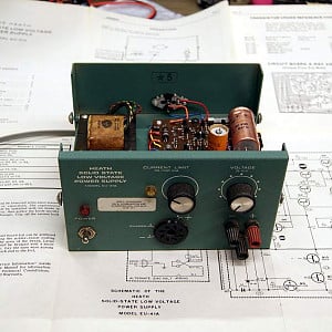
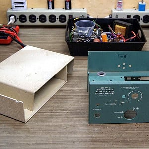
Here's the Heathkit before I start taking it apart. I will have to dig through my box of knobs to see if I have anything better or whether I need to order some.


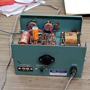
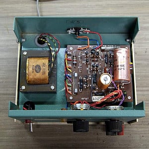
I had been hoping to use the original transformer but the first thing I noticed when I took the covers off is how small it is.Then I realized the EU-41A's maximum output was only 15V 750mA. It's transformer is the right voltage for the "red" but I'd prefer to have more current available. I don't have anything suitable in the box of transformers so I looked online. Wow, transformers are a lot more expensive than I remembered.
But switching power supplies aren't so I opened a thread to ask and ordered one. Discussion ensued so I thought it best to start this Project Log so that the discussion could continue in its discussion thread.
Jan 22 2022 Quick update:
I got busy this week. The original knobs are 1/2 moon and the new pots are split shaft so they won't work. I like the idea of using a red knob for voltage and a blue one for current as seen on the similar project linked below so I ordered some knobs (10 of each were only about $1 more than 1 of each so I'll have some for future projects).

Now that it is apart I started thinking about the new layout. I originally thought I'd just make the hole from the octal socket fit the meter and live with it there but the hole is wider than the meter so I'll make a faceplate and put things where I like. I have a few ideas but I won't finalize anything until the switching supply gets here.
I also realized that there are no nuts for the pots in the kit so I spent over an hour searching everywhere for some before I realized that I have another project hanging over the bench with similar pots that had 2 nuts for each. It also has 2 knobs that are the same as I ordered but white so I'll use them until the right ones get here.
Feb. 3 2022
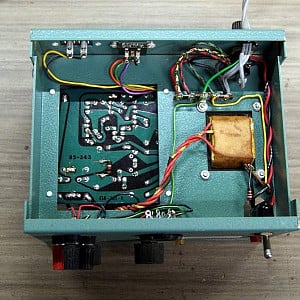
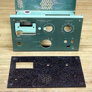
I think I have almost all of the mods to the case done. The holes for the pots, switch and binding posts were in good locations but the pots and switch I'm going to use need smaller holes so I cut an overlay from 3mm ABS sheet. I intended to just cover the hole from the octal socket but decided it would be a good place for an inlet vent (the fan can only push out as much air as the vents let in). The rectangular hole is for the meter (I've looked at several websites and YouTube videos about these kits and apparently the specific voltmeter/ammeter I happened to have is very popular for use with these power supplies.

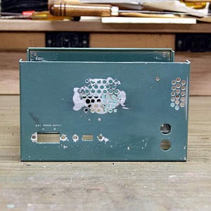
The large area of holes near the centre of the back are where the fan will be mounted. If you look carefully you may notice that 4 of the holes are larger and not quite where they should be because that's where the Heathkit's TO3 power transistor was. The small hole near the inlet vent on the right is where the power transistor will go. The case is made of 1.6mm thick aluminum and the back is approx. 210 sq.cm (33.75 sq.in) less the holes.
I am thinking about adding a finned heat sink behind the power transistor too.
I haven't decided what to do with the holes from the terminals and switch Heath provided for external programming yet. I'll probably cover the smaller one but the switching power supply will be right in front of the larger one so I will probably turn it into another inlet vent.

Ancient history: When I was in school about half a century ago someone put me in contact with a widow who wanted her late husband's electronics stuff to go to someone who would get some use from it. One of the items I bought from her was a Heathkit EU-41A bench power supply.
A few years ago it stopped working. I wasn't doing a lot of electronics at the time so I put it aside to see if I could fix it later.
Recent history: Last year when it became apparent that I was actually going to have a place to work on electronics I started thinking about the equipment I would need and I bought one of the 30V 3A "red" power supply kits that are all over eBay but before it arrived the weather had warmed up and I was working in the garden and the garage so I put it aside for this winter. One if the summer's projects was re-organizing the garage shop and when I came across the Heathkit it occurred to me that putting the new kit inside the old case should give me what I need.
I also have a digital voltmeter/ammeter that I bought for another project and didn't use so adding it to the front of the case will be a definite upgrade.
Here's the Heathkit before I start taking it apart. I will have to dig through my box of knobs to see if I have anything better or whether I need to order some.
I had been hoping to use the original transformer but the first thing I noticed when I took the covers off is how small it is.Then I realized the EU-41A's maximum output was only 15V 750mA. It's transformer is the right voltage for the "red" but I'd prefer to have more current available. I don't have anything suitable in the box of transformers so I looked online. Wow, transformers are a lot more expensive than I remembered.
But switching power supplies aren't so I opened a thread to ask and ordered one. Discussion ensued so I thought it best to start this Project Log so that the discussion could continue in its discussion thread.
Jan 22 2022 Quick update:
I got busy this week. The original knobs are 1/2 moon and the new pots are split shaft so they won't work. I like the idea of using a red knob for voltage and a blue one for current as seen on the similar project linked below so I ordered some knobs (10 of each were only about $1 more than 1 of each so I'll have some for future projects).
Now that it is apart I started thinking about the new layout. I originally thought I'd just make the hole from the octal socket fit the meter and live with it there but the hole is wider than the meter so I'll make a faceplate and put things where I like. I have a few ideas but I won't finalize anything until the switching supply gets here.
I also realized that there are no nuts for the pots in the kit so I spent over an hour searching everywhere for some before I realized that I have another project hanging over the bench with similar pots that had 2 nuts for each. It also has 2 knobs that are the same as I ordered but white so I'll use them until the right ones get here.
Feb. 3 2022
I think I have almost all of the mods to the case done. The holes for the pots, switch and binding posts were in good locations but the pots and switch I'm going to use need smaller holes so I cut an overlay from 3mm ABS sheet. I intended to just cover the hole from the octal socket but decided it would be a good place for an inlet vent (the fan can only push out as much air as the vents let in). The rectangular hole is for the meter (I've looked at several websites and YouTube videos about these kits and apparently the specific voltmeter/ammeter I happened to have is very popular for use with these power supplies.
The large area of holes near the centre of the back are where the fan will be mounted. If you look carefully you may notice that 4 of the holes are larger and not quite where they should be because that's where the Heathkit's TO3 power transistor was. The small hole near the inlet vent on the right is where the power transistor will go. The case is made of 1.6mm thick aluminum and the back is approx. 210 sq.cm (33.75 sq.in) less the holes.
I am thinking about adding a finned heat sink behind the power transistor too.
I haven't decided what to do with the holes from the terminals and switch Heath provided for external programming yet. I'll probably cover the smaller one but the switching power supply will be right in front of the larger one so I will probably turn it into another inlet vent.