Maker Pro
Maker Pro

I want to make a speed limiter for my motorcycle

danadak

Feb 19, 2021
780
Joined
Feb 19, 2021
Messages
780
You cannot switch the coil directly with Uno.

Post the wiring diagram you have for the bike, and its maintenance manual if you
have that.

You can consider coding using block programming. mBlock takes your block configuration
and generates Arduino code from that.

1688488856392.png

The above code is basic, should work. But I would add hysteresis to it. If code trips
at 5000 then ignition comes bak on at. say, 4900 RPM, 100 RPM is the hysteresis.
That helps with noise issues from RPM sensor. Easy to code and add.

Here is code it generated that you program into part using Arduino IDE :
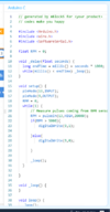
1688488927063.png

Your interface to the RPM sensor has to meet logic levels allowed into Arduino. Do
you have an oscilloscope ?

Regards, Dana.
 
Last edited:

SaadCDI

Jun 9, 2023
7
Joined
Jun 9, 2023
Messages
7
You cannot switch the coil directly with Uno.

Post the wiring diagram you have for the bike, and its maintenance manual if you
have that.

You can consider coding using block programming. mBlock takes your block configuration
and generates Arduino code from that.

View attachment 59721

The above code is basic, should work. But I would add hysteresis to it. If code trips
at 5000 then ignition comes bak on at. say, 4900 RPM, 100 RPM is the hysteresis.
That helps with noise issues from RPM sensor. Easy to code and add.

Here is code it generated that you program into part using Arduino IDE :

View attachment 59722

Your interface to the RPM sensor has to meet logic levels allowed into Arduino. Do
you have an oscilloscope ?

Regards, Dana.
Dear Dana,

I hope this message finds you well. Firstly, I want to express my gratitude for your reminder about our project. I had completely forgotten about it amidst some personal matters that demanded my attention.

Thank you so much for your patience during this time. Now that things have settled down, I'm excited to explore mBlock—it's something I've always been curious about but never quite understood. I'll start researching it right away to see how we can use it to our advantage.
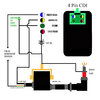
This is the CDI diagram.

Looking forward to diving back into the project with renewed energy!

Best regards.
 

Attachments

  • CDI Lihua diagram.jpg
    CDI Lihua diagram.jpg
    295.5 KB · Views: 4
Last edited:

SaadCDI

Jun 9, 2023
7
Joined
Jun 9, 2023
Messages
7
You cannot switch the coil directly with Uno.

Post the wiring diagram you have for the bike, and its maintenance manual if you
have that.

You can consider coding using block programming. mBlock takes your block configuration
and generates Arduino code from that.

View attachment 59721

The above code is basic, should work. But I would add hysteresis to it. If code trips
at 5000 then ignition comes bak on at. say, 4900 RPM, 100 RPM is the hysteresis.
That helps with noise issues from RPM sensor. Easy to code and add.

Here is code it generated that you program into part using Arduino IDE :

View attachment 59722

Your interface to the RPM sensor has to meet logic levels allowed into Arduino. Do
you have an oscilloscope ?

Regards, Dana.
I recently came across a video that sparked an idea about implementing a rev limiter for my engine using a microcontroller, potentially an Arduino. The plan is to utilize the RPM signal from the spark wire and adjust the code to establish an RPM limit.

I'm contemplating whether grounding the "extra" RPM beyond the set limit, like 1000 RPM above 5000 RPM, using a relay would be a simpler solution. It seems feasible, but I'm seeking your input on this matter.

Thank you in advance for your thoughts.
 

danadak

Feb 19, 2021
780
Joined
Feb 19, 2021
Messages
780
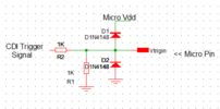
You might use the trigger sig to the CDI as its probably a low V and more
suitable for micro interface. It may need R divider attenuation, and I would
clamp the signal (after the divider), at the micro input.

1710117707265.png

Adjust divider R's to produce spec logic levle input for micro.

I would gate the trigger signal to the CDI for suppression. Small signal relay
should be fine, just check its dropout delay. Code should incorporate hysterisis
before turning ignition back on.

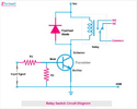
Relay drive :


1710117836675.png


R2 ~ 10K, R1 set it to supply Ibase = Irelay / 10, R = (Voutmicrohigh - Vbe) / Ibase
Basically driving 1/10 the relay current into the base to insure transistor is saturated.
R2 is to insure when micro starts up and its output pins undefined, transistor stays off
until under program control.

Regards, Dana.

PS : Second thought :

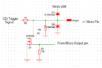
I would add one consideration, a relay's contacts bounce, so using
a MOSFET to gate trigger signal might be a better choice, but try it with a
relay. Note the 2N7000 might be better replaced by a better (lower) Rdson
MOSFET (2N7002) at the gate drive level out of Arduino, check that out.


1710119916875.png
 
Last edited:

Bluejets

Oct 5, 2014
6,958
Joined
Oct 5, 2014
Messages
6,958
All motorcycles have a kill switch...bridge that with a set of relay contacts.....not as though it has to switch in and out at high frequency.
Simply add some amount of deadband so it doesn't cut in and out at some crazy rate.
Have to ask again though, is this to minimise over rev of engine or over speed of the machine?
 

Externet

Aug 24, 2009
892
Joined
Aug 24, 2009
Messages
892
My old cars with modern transmissions use now a circuit I made with a LM2907 chips to engage the TCC at a certain driveshaft speed. Such chip can be used for your task by shutting down the ignition or control something ...
 

SaadCDI

Jun 9, 2023
7
Joined
Jun 9, 2023
Messages
7
All motorcycles have a kill switch...bridge that with a set of relay contacts.....not as though it has to switch in and out at high frequency.
Simply add some amount of deadband so it doesn't cut in and out at some crazy rate.
Have to ask again though, is this to minimise over rev of engine or over speed of the machine?
my motorcycle has a killswitch that i can use to cut off the ignition and the goal is to limit the over rev of the engine.
 

SaadCDI

Jun 9, 2023
7
Joined
Jun 9, 2023
Messages
7
You might use the trigger sig to the CDI as its probably a low V and more
suitable for micro interface. It may need R divider attenuation, and I would
clamp the signal (after the divider), at the micro input.

View attachment 63031

Adjust divider R's to produce spec logic levle input for micro.

I would gate the trigger signal to the CDI for suppression. Small signal relay
should be fine, just check its dropout delay. Code should incorporate hysterisis
before turning ignition back on.

Relay drive :


View attachment 63032


R2 ~ 10K, R1 set it to supply Ibase = Irelay / 10, R = (Voutmicrohigh - Vbe) / Ibase
Basically driving 1/10 the relay current into the base to insure transistor is saturated.
R2 is to insure when micro starts up and its output pins undefined, transistor stays off
until under program control.

Regards, Dana.

PS : Second thought :

I would add one consideration, a relay's contacts bounce, so using
a MOSFET to gate trigger signal might be a better choice, but try it with a
relay. Note the 2N7000 might be better replaced by a better (lower) Rdson
MOSFET (2N7002) at the gate drive level out of Arduino, check that out.


View attachment 63033
Hey there,

I stumbled upon this video that nails down RPM sensing perfectly. The method they use to capture the signal through electromagnetic effect seems straightforward, especially with the filtering circuit they employ. I'm thinking of adopting the circuit from the video, given its simplicity.

Now that I have the RPM sensing aspect sorted, my next step is to tweak the program outlined in the video's description. My aim is to activate a relay that will cut off the ignition. Interestingly, I've already set up a simple kill switch between the ignition coil and the spark, and that's where I plan to place the relay.

I should mention that while I have a basic understanding of electronic circuits, I'm not too advanced in this area. However, I've been experimenting with mBlock, and it seems incredibly helpful.

Thank you for providing the circuit from the video. I greatly appreciate your guidance and support in this project.

Here's the link to the video:

Looking forward to hearing your thoughts!

Best regards,
 

SaadCDI

Jun 9, 2023
7
Joined
Jun 9, 2023
Messages
7
My old cars with modern transmissions use now a circuit I made with a LM2907 chips to engage the TCC at a certain driveshaft speed. Such chip can be used for your task by shutting down the ignition or control something ...
Hey there,

I stumbled upon a video featuring a simple circuit for RPM sensing. While I'm not an expert in electronics and only have a basic understanding, I did some research on the LM2907 chip mentioned in the video. It seems like a good idea to use it to transform frequency into voltage.

The circuit simplicity caught my attention, and incorporating the LM2907 chip for frequency to voltage conversion sounds promising. I believe this approach could be quite effective for the project.

Video link:

Best regards
 

Delta Prime

Jul 29, 2020
2,002
Joined
Jul 29, 2020
Messages
2,002
no it's me i just lost the other account.
Intriguing! I do not believe you are. Your demeanor has changed.
There is a mystery of foot.
The only man alive who can rival Sherlock Ohm's intellect.
(Yours truly)
Is the notorious.
Professor James Moriarty.
You are free to go, for now...
:cool:
I love this thread you started,thank you. Vroom vroom.
 

Bluejets

Oct 5, 2014
6,958
Joined
Oct 5, 2014
Messages
6,958
Well, if you cut the engine at certain rpm via the "simple method using ignition kill switch" .....you have all you need.
That was my point all along.
 

Ducatimonster

Jul 2, 2023
13
Joined
Jul 2, 2023
Messages
13
Well, if you cut the engine at certain rpm via the "simple method using ignition kill switch" .....you have all you need.
That was my point all along.
How will the arduino know the exact rpm of the engine and tap in the kill switch wire to ground the spark signal ?
 

Bluejets

Oct 5, 2014
6,958
Joined
Oct 5, 2014
Messages
6,958
That's for you to work out as there are many ways depending on your motorcycle setup.
Suffice to say there would be litterally thousands of Arduino projects out there on how to tap the rpm.
Once you find one, you adapt the circuit and the sketch to suit your requirements.
No one is going to do your work for you and then say here ya go snowflake, thanks for coming.
I showed an easy way to kill the ignition without being intrusive on any existing pcb gear.
Suggestion for detecting rpm might be wrap a wire around one spark lead and go from there with the Arduino and relay output.
 

Delta Prime

Jul 29, 2020
2,002
Joined
Jul 29, 2020
Messages
2,002
Screenshot_20240313_210955.jpg

Here's a snippet from the Arduino forum .
If the duty cycle is fixed you can just use the pulseIn() function to measure the length of the pulse. From that you can calculate everything else.
http://arduino.cc/en/Reference/PulseIn 36
#define MICROSECONDS_PER_MINUTE (60UL*1000000UL)
#define PULSES_PER_REVOLUTION 128 /* You'll have to figure this out */
int rpm(int inputPin) {
unsigned long pulseLength = pulseIn(inputPin, HIGH); // Microseconds per pulse
pulseLength = (pulseLength * 100) / 30; // Convert from 30% to 100%
unsigned long pulseRate = MICROSECONDS_PER_MINUTE / pulseLength; // Pulses per minute
return pulseRate / PULSES_PER_REVOLUTION
By the way I strongly suggest you ask your questions on all about circuits! They have an order of magnitude more members than this site. They are consummate professionals unlike myself... as you can clearly tell...I am not alone.
Screenshot_20240313_210858.jpg
RPM limiter, speed limiter, title of your thread? Are you open to other suggestions?
 
Last edited:

Bluejets

Oct 5, 2014
6,958
Joined
Oct 5, 2014
Messages
6,958
The whole idea of a rev limiter on any motorcycle used for everyday commuting is just plain ludcris.
Rev limiters are used in situations where engine revs continually approach critical piston speed as in GrandPrix racing and the operator has their attention on near maximum performance for hours on end.
No time to be distracted by continually looking down at rev guages.
In fact anything that automatically cuts power to an engine in domestic use would be considered a safety issue.
 

danadak

Feb 19, 2021
780
Joined
Feb 19, 2021
Messages
780
How will the arduino know the exact rpm of the engine and tap in the kill switch wire to ground the spark signal ?

Post # 24 is way to go becuse you avoid the HV of spark plug wire. Do you
have a scope so you can look at signal from crank sensor that goes to CDI
to trigger the spark ?

Note whatever way you do this you can use rate of change sensing in code
to see if RPM is going to become excessive even though its not there yet.
By this I mean if RPM is on a ramp, say 1000 rpm over 1 secs, and you are
at 4000 RPM, say the limit is 7,000 rpm, then in 3 secs you will be at limit.
So you dont have to be at limit to know you are going to hit limit. This
helps in managing delays in the design due to inertia, time to measure RPM
(eg. frequency of trigger signal to CDI, the "gate" time over which you count
pulses to comute frequency), etc..


Regards, Dana.
 
Top