Hi all. I have tried to find a definitive answer to my question on my own, however, I am not confident in what I have found. This was my last, but obviously, most trusted attempt.
I realize substituting capacitors with higher voltage and temperature ratings is acceptable, if you cannot find the exact spec replacements, but I am trying to replace a cap that I cannot find the same uF rating for. I've tried the common online supply stores (Digikey, Mouser, Arrow) and ebay and amazon. No luck.
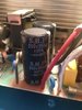
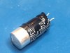
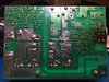
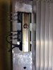
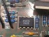
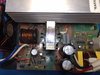
It is a 950uF/200V snap in cap. 2" long, 1" diameter, 10mm lead spacing. There are tons of 1000uF's with the correct dimensions, and those would be very close, considering there is often a 10-20% tolerance with these things. So my question is, would I be able to get away with a 1000uF (or other suggested option) cap in place of this, or does that alter the eventual DC output voltage of the unit? There are two of them on the board and the application is for an RV power supply from 110vac to 12vdc, so it both powers the 12 volt electronics in the RV and acts as a house battery charger when plugged into AC. Note that the circuit board does list the cap values under the removed caps. 950uF/200V.
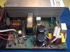
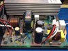
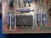
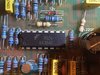
Pics of the board and the cap are attached. If it matters, the mains are on the right side of that board and the DC output on the left (white and blue wires).
Thanks in advance for what I'm sure will be another interesting education.")
I realize substituting capacitors with higher voltage and temperature ratings is acceptable, if you cannot find the exact spec replacements, but I am trying to replace a cap that I cannot find the same uF rating for. I've tried the common online supply stores (Digikey, Mouser, Arrow) and ebay and amazon. No luck.
It is a 950uF/200V snap in cap. 2" long, 1" diameter, 10mm lead spacing. There are tons of 1000uF's with the correct dimensions, and those would be very close, considering there is often a 10-20% tolerance with these things. So my question is, would I be able to get away with a 1000uF (or other suggested option) cap in place of this, or does that alter the eventual DC output voltage of the unit? There are two of them on the board and the application is for an RV power supply from 110vac to 12vdc, so it both powers the 12 volt electronics in the RV and acts as a house battery charger when plugged into AC. Note that the circuit board does list the cap values under the removed caps. 950uF/200V.
Pics of the board and the cap are attached. If it matters, the mains are on the right side of that board and the DC output on the left (white and blue wires).
Thanks in advance for what I'm sure will be another interesting education.