Maker Pro

Practical vacuum tube signal generator

This generator will produce two fixed frequency signals to test electronic devices. It is based on vacuum tubes

Miguel Lopez

Jan 25, 2012
255
Joined
Jan 25, 2012
Messages
255
Miguel Lopez submitted a new Project Log:

Practical vacuum tube signal generator

Hello everybody

I've been out of touch on valves due to time restrictions, but I want to share with you a small project that I just recently started.

I have always had plans to build a second valve oscilloscope and a powerful audio amplifier (with 807s). Mr Time had been implacable, so I've been a little distanced from valves for a while. But now I want to work on a project which is a device to be used with those both bigger (and future) projects.

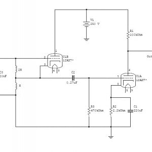
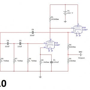
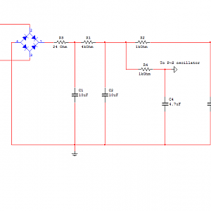
It is my intention to build a signal generator with two fixed outputs: one at 1kHz and the other at 25kHz. The first one will be to test valve amplifiers while the second it's intended to help in the design of the EHT generator for the scope.

This way I can work with valves (which is something I love), and at the same time I can build a useful tool for future projects. It's a win-win situation. On the other hand as Mr Time is always flying away from me, I want to use parts that I have built before for other abandoned (or modified) projects.

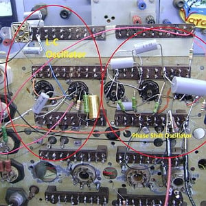
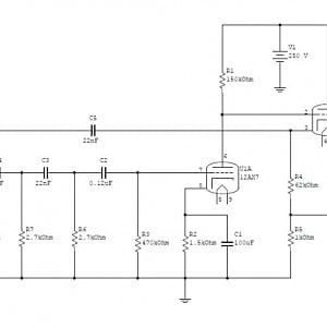
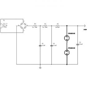
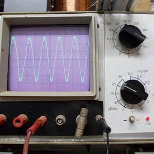
I also want to experiment with new circuits (for me) so, I want to build the 1 kHz signal with a phase shift oscillator, while the 25kHz will be an L-C oscillator. This way a can "play" with valves too. I have tested those circuits in my valve tester board (which I call "High Tension Bread Board" or HTBB)

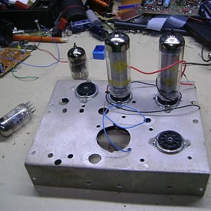
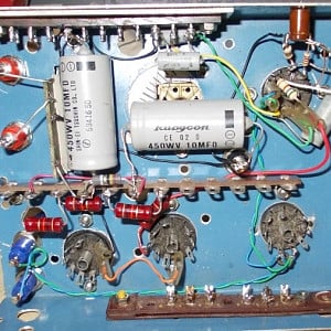
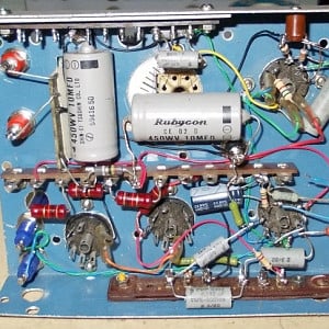
The attached pictures show the chassis in which I will mount the generator, and the circuit tested on the HTBB.

Read more about this project log here...
 

hevans1944

Hop - AC8NS
Jun 21, 2012
4,880
Joined
Jun 21, 2012
Messages
4,880
I envy your access to vacuum tube (valve) technology. Except for a few RF power tubes, I gave away my collection of valves years ago to someone who restores vintage radios from the 1920s. IIRC, one of the first audio oscillators I built was a three-stage, RC, phase-shift oscillator that coupled the output from the plate of one valve (half of a 6SN7 probably) to its control grid. Easy peasy, but not so easy to change the frequency of oscillation.

Years later, when I needed an audio frequency oscillator with a low-distortion sinusoidal output for a one-off project, I used an LC circuit, winding the inductor by hand on a small toroid core, then digitally dividing the high-frequency oscillator frequency and phase-locking it to a sine-triangle-square wave voltage-controlled oscillator integrated circuit. The hardest part was figuring out the division ratios needed for an equally-tempered 12-note musical scale spanning a couple of octaves.

I wanted (needed) sinusoidal audio wave forms because this was part of a psychology experiment that explored how children of various ages learned audio sound sequences. We didn't want to confuse the issue with harmonics because its difficult to separate stimulus from response in the auditory modality. The "only" variables were the pitch, duration, and sequence of the notes the children heard through earphones. Each child would listen to a "test" sequence (as many times as desired) and try to determine which one of six "trial" sequences matched the "test" sequence. Pretty diabolical I would say, but I just built the equipment and never got involved in the field trials.

Today of course this would all be done with software on a laptop personal computer, but it was pretty much novel "state-of-the-art" in the 1960s. And a real hoot and pleasure to work on.

You can save yourself some time and trouble by salvaging the fly-back transformer from a CRT-based TV. Find it's resonance frequency (somewhere around 17.25 kHz) and build your high-frequency EHT oscillator to match. Some of these (especially the color TV versions) had diode multipliers "built in" to the fly-back transformer package, which can also be quite useful.

Make sure not to pick an obsolete CRT for which you can't find a replacement. Oh, wait! Are not ALL CRTs obsolete now? No, there is at least one company still carrying on with their manufacture. Read all about it here.

Good luck on your projects! Please post some more photos as you progress. Maybe we can help revive an interest in vacuum tubes with the current generation of budding electrical and electronic engineers! BTW, AFAIK there is NO substitute for vacuum tubes when really high-power RF generation is required... everything from low-frequency induction heaters to microwave traveling wave tubes (TWTs), klystrons, magnetrons... and everything in between when a few megawatts are needed. Oh, and cyclotrons too of course.

Hop
 

Miguel Lopez

Jan 25, 2012
255
Joined
Jan 25, 2012
Messages
255
Here an update from yesterday. The LC oscillator is already working on the chassis with 6N2P double triodes. The PS oscillator is not connected yet.
 
Last edited:
Top