-
Categories
-
Platforms
-
Content
You are using an out of date browser. It may not display this or other websites correctly.
You should upgrade or use an alternative browser.
You should upgrade or use an alternative browser.
Scroll to continue with content
- Joined
- Nov 17, 2011
- Messages
- 13,769
In principle yes - depending on what it is supposed to do.Would this IR circuit work for an Arduino?
Add a 1 µF or bigger capacitor between 5 V and GND. This will help to supply curent peaks when the LEDs are turned on.I've seen capacitors added to similar circuits,
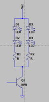
You can improve the efficiency of the circuit considerably: Instead of using two IR-LEDs in parallel, put them in series. The voltage drop will increase from ~ 1.6 V to ~3.2 V, therefore reduce the series resistance accordingly. Like so:

You will then need only 4 transistors and the base current (drive current from the Arduino output) will be reduced accordingly. With 4 transistors you can increase the number of LEDs to 16 instead of the 14 you have now. Or use 14 LEDs, the last transistor will then drive only 2 LEDs, not 4.
Awesome, Thank you for the info! Would you by chance know if I would have to increase the ohm value and for a 16 LED circuit, would you by chance know the current draw? Would this circuit work on a 300mA supply?In principle yes - depending on what it is supposed to do.
Add a 1 µF or bigger capacitor between 5 V and GND. This will help to supply curent peaks when the LEDs are turned on.
You can improve the efficiency of the circuit considerably: Instead of using two IR-LEDs in parallel, put them in series. The voltage drop will increase from ~ 1.6 V to ~3.2 V, therefore reduce the series resistance accordingly. Like so:
View attachment 61236
You will then need only 4 transistors and the base current (drive current from the Arduino output) will be reduced accordingly. With 4 transistors you can increase the number of LEDs to 16 instead of the 14 you have now. Or use 14 LEDs, the last transistor will then drive only 2 LEDs, not 4.
Martaine2005
- May 12, 2015
- 4,957
- Joined
- May 12, 2015
- Messages
- 4,957
Use Ohms law to calculate the total current.
Or make the circuit and measure the total current.
But you have to specify what brightness you require therefore altering the mA to each LED.
You may find that 5mA is bright enough or 15mA etc.
Have a good read HERE to get a good understanding.
We use V for voltage so V=IxR whereas the formula from Fluke use E for voltage so E=IxR (same thing).
Martin
- Joined
- Nov 17, 2011
- Messages
- 13,769
We have a resource on driving LEDs. Read all the info you need there.Would you by chance know if I would have to increase the ohm value and for a 16 LED circuit,
When you add 2 LEDs in series, as I proposed, the voltage drop across the resistor is less than with a single LED. Therefore the resistance needs to be lower for the same current.
That's up to you. You define the current through the LEDs, then calculate the resistors accordingly, see the resource I linked.would you by chance know the current draw?
In your circuit you have ILED = (5 V -1.6 V)/ 220 Ω = 15 mA (1.6 V being the typical voltage drop across an IR-LED).
With 2 LEDs in series the calculation goes: R = VR / ILED = (5 V - 2 × 1.6 V) / 15 mA = 120 Ω
Hello,
IR leds may have different specs than standard leds.
There are IR leds that allow peak currents of 100 mA.
Read the datasheet of your IR led for a decent current.
Have a look at the attached VISHAY datasheets.
Bertus
IR leds may have different specs than standard leds.
There are IR leds that allow peak currents of 100 mA.
Read the datasheet of your IR led for a decent current.
Have a look at the attached VISHAY datasheets.
Bertus
Attachments
roughshawd
- Jul 13, 2020
- 470
- Joined
- Jul 13, 2020
- Messages
- 470
When you decide on the reason behind having all these LEDs, maybe you should add a dimmer and a terminator to the line so it doesn't do ump every thing to ground when you turn it on. They say diodes are a good choice, and functional circuits are important to stay in the loop.
- Joined
- Nov 17, 2011
- Messages
- 13,769
It is not.Is that ok?
An Arduino can supply 20 mA continuously, 40 mA peak.
Here's where my scheme from post #2 comes in handy by reducing the current requirements from the Arduino's output pin by a factor of 2.
Similar threads
- Replies
- 21
- Views
- 1K
- Replies
- 5
- Views
- 773
- Replies
- 3
- Views
- 1K
- Replies
- 2
- Views
- 908

